Span and Deflection
- For uniformly distributed loads the deflection of a beam is proportional to its span to the power of four and for a concentrated load the deflection is proportional to its span to the power of three.
- To reduce deflections, an increase in the depth of a beam is more effective than an increase its width ( for a rectangular cross-section)
Model Demonstrations
Effect of spans
This demonstration shows the effects of span and second moment of area of a beam on its deflections.
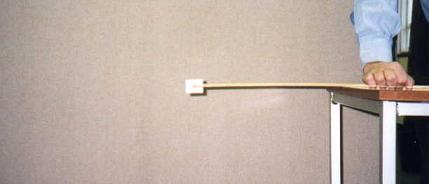
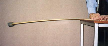
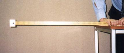
Fig. 7-3: Deflections of a cantilever beam subjected to a concentrated load
A one-metre wooden ruler with cross section 5 mm by 30 mm is used and a metal block is attached to one of its two ends. One end of the ruler, with the long side of the cross section horizontal, is supported to create a cantilever with the concentrated load at its free end.
1. Observe the displacement at the free end of the cantilever with a span of say 350 mm. It can be seen from Fig. 7-3a that there is small deflection at the free end.
2. Double the span to 700 mm as shown in Fig. 7-3b and a much larger end displacement is observed. According to the results presented in Section 7.2, the end deflection for a span of 700 mm should be eight times that for a span of 350 mm when the effect of the self-weight of the ruler is negligible in comparison to the weight of the metal block.
3. Turn the ruler through 90 degrees about its longitudinal axis as shown in Fig 7-3c and repeat the tests when much reduced end displacement will be seen. The formula in Table 7.1 shows that deflection is proportional to the inverse of the second moment of area which for a rectangular section is given by ![]() . For the current test, the second moment of area of the section about the horizontal axis is 36 times that of the section used in the last test, resulting in maximum deflections of about one thirty-sixth of those in the second test (Fig. 7-3b).
. For the current test, the second moment of area of the section about the horizontal axis is 36 times that of the section used in the last test, resulting in maximum deflections of about one thirty-sixth of those in the second test (Fig. 7-3b).
Effect of boundary conditions
This demonstration shows the effects of the boundary conditions, or supports, of a uniform beam on its deflections and shows that fixed boundary conditions produce a stiffer beam than do pinned boundary conditions.
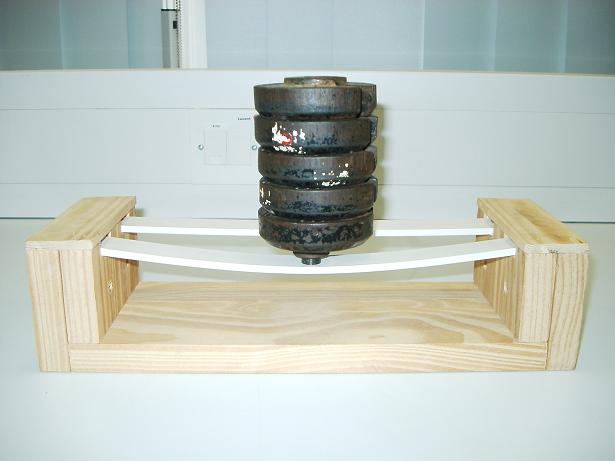
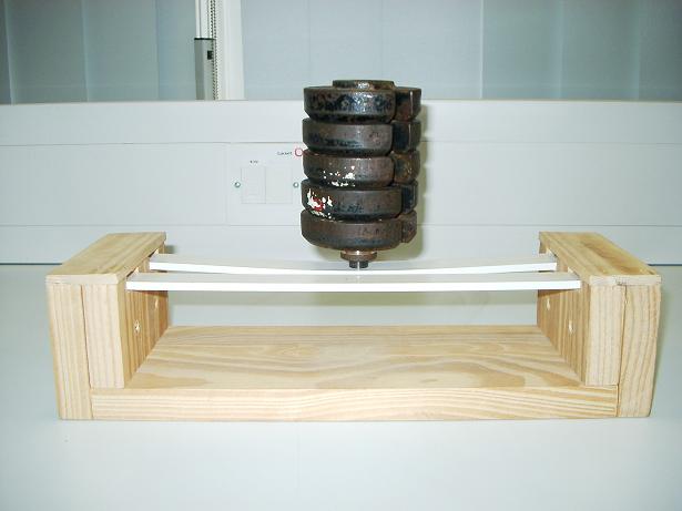
Fig. 7-4: Effect of boundary conditions
Fig. 7-4 shows the demonstration model which comprises a wooden frame and two plastic strips with the same length and cross-section. For the fixed beam, a plastic strip is attached securely to the frame with screws and glue at each end and for the simply supported beam a plastic strip is encased at its ends which are free to rotate.
A qualitative demonstration can be quickly conducted. Pressing down at the centres of each of the two beams it is possible to feel qualitatively the difference in the stiffnesses of the two beams. Based on the results in Table 7-1, the fixed beam is four times as stiff as the simply supported beam.
The loads applied and the deflections produced can be quantified. For a particular set of plastic strips, it is found that a concentrated load of 22.3 N produces a measured maximum deflection under the load of 3.5 mm for the beam with the fixed ends whereas for the simply supported beam the maximum deflection is measured to be 13.0 mm. The ratio of the measured displacements is the same as the theoretical ratio.
The bending moment at one fixed end of a beam
This demonstration shows how the end moment in a fixed beam can be measured.
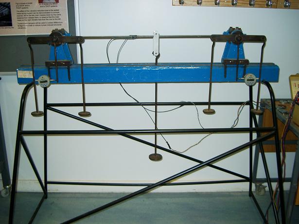
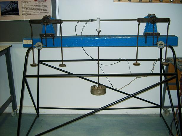
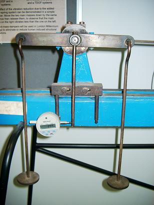
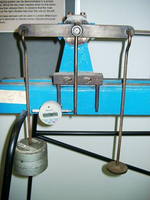
Fig. 7-5: Bending moments at the fixed ends of a uniform beam
At the fixed end of a beam, both the displacement and the rotation, or slope, are zero. Using the condition that the slope at a fixed end equals zero, a fixed end condition can be created and the moment associated with this condition can be determined.
Fig. 7-5a shows a simply supported beam with a supporting frame. A hanger is placed at the centre of the beam so loads can be added. The ends of two vertical arms at the supports are attached to displacement gauges. Readings from the gauges divided by the lengths of the arms are the end rotations of the beam. If weights are placed on two end hangers, they will induce rotations in the opposite directions to those induced by the load applied at the centre of the beam. When the readings in the gauges are reduced to zero, a beam with two fixed ends has been created and the fixed end moments are the products of the weights on the hanger and the horizontal distances between the ends of the hangers and the supports.
Fig. 7-5b shows a mass of 5 kg placed on the hanger at the centre of the beam and Fig. 7-5c shows the rotation of the beam at the left support and the reading of 2.99 mm. By adding a mass of 3 kg at to each of the two end hangers (Fig. 7-5d), the gauge at the left end shows a reading of 0.01 mm, indicating that a fixed boundary condition has been created. The associated fixed end moment is 3×9.81×0.125 (the distance between the end hanger and the support) = 3.68 N.m in this case.
Lateral stiffness of vertical members
This model compares the relative stiffness of a cantilever and the stiffness of a beam with both ends clamped and investigates apparent errors in the demonstration.
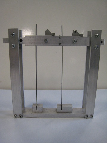
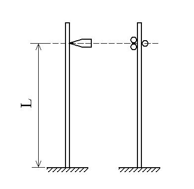
Figure 7.A1
The model is shown in Figure 7.A1a. Two pairs of vertical aluminum members are rigidly connected to the base member. Two identical steel strips are placed vertically and clamped at their base. A horizontal member is located at upper part of and between the vertical members. This can move in the horizontal direction along the guides of ball bearings. There are two elements in the middle of the horizontal member which can be flapped down independently to form the loading points and the boundary conditions shown in Figure 7.A1b. A mechanical force gauge is used to apply and read the horizontal force on the right end of the horizontal member.
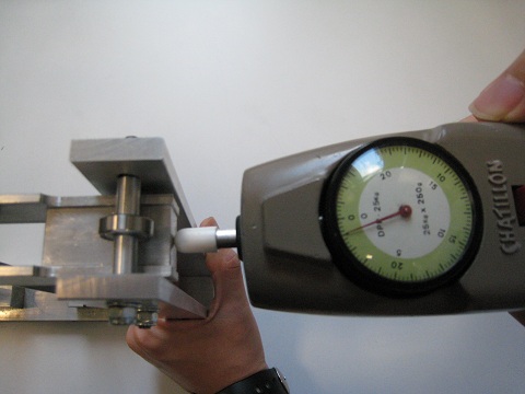
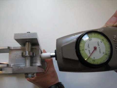
Figure 7.A2: The readings of the loads on the two columns
Figure 7.A2 shows the readings when the forces are applied to the cantilever and the beam with the fixed top end. For the cantilever the gauge reads about 4 x 0.25 x 9.81 = 10 N and for the fixed beam it reads about 12 x 0.25 x 9.81 = 30 N. In other words, the lateral stiffness of the fixed beam is about 3 times that of the cantilever. However, the theory of beams predicts a ratio of stiffness of 4 [7.3]. What is wrong?
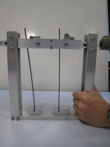
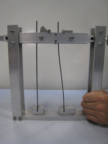
Figure 7.A3: Deformations of the two members
Figure 7.A3 shows the deformed shapes of the two vertical members subjected to the above loading. It can be observed that the fixed boundary condition is effectively not fully realized as some rotation occurs at the top end of the apparently fixed beam. This is due to the design of the device as indicated on the right part in Figure 7.A1b the three roller fixings do not form a true fixed boundary condition and hence the stiffness of the member is not that of one with true fixed end.
Practical Examples
Column supports
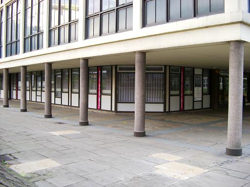
Floors which extend outside normal building lines can seldom act as cantilevers due to the effect of the relationship between span, deflection and loading, and thus need additional column supports as shown in Fig. 7-6.
The Phenomenon of prop roots

In rain forests, plants such as Ficus have prop roots. In the humid and shaded conditions, when the large branches reach a certain length, aerial roots grow downwards from the branches. When these aerial roots reach the ground they are similar to stems that support upper branches, forming the unique phenomenon of prop roots.
The prop roots provide the necessary and additional vertical supports to the branches of the tree allowing them to extend their spans further.
Metal props used in structures
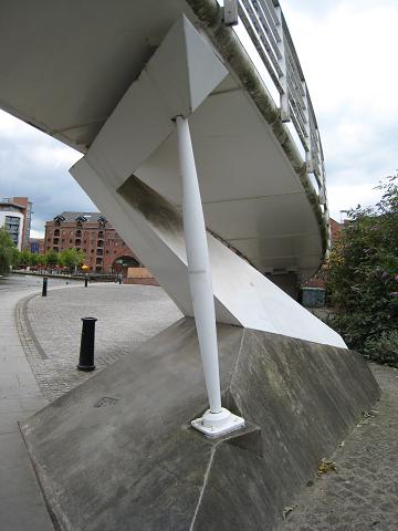
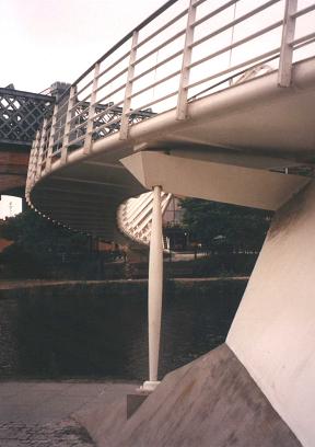
Fig. 7-8: Props used to support a footbridge
The most effective ways to increase the stiffnesses or reduce the deflections of a structure are to reduce spans or to add supports, as shown in the last example obtained from nature.
The Cardiff Millennium Stadium was selected to hold the Eve of the Millennium concert on 31 December 1999. However, the Stadium was designed for sports events rather than for pop concerts. During pop concerts, spectators bounce and jump in time to the music beat and produce dynamic loading on the structure which is larger than the loading due to their static weight. If one of the music beat frequencies occurs at or is close to one of the natural frequencies of the cantilever structure, resonance or excessive vibration may occur, which affects both the safety and the serviceability of the structure.
To enable the Eve of the Millennium concert to take place, the cantilever structure of the Cardiff Millennium Stadium had to be reinforced with temporary metal props, which are similar to the prop roots in Section 7.4.2. In this way, the spans of the cantilevers were effectively reduced and consequently their stiffnesses and natural frequencies were increased above the range where any unacceptable resonance induced by the spectators was possible.
Fig. 7-8 shows a steel prop used to support the deck of a footbridge, which is a critical structural member to the bridge.
References
7.1 Hibbeler, R C, (2005), Mechanics of Materials, Sixth Edition, Prentice-Hall Inc, Sigapore, ISBN 0-13-186-638-9.
7.2 Williams M S and Todd J D, (2000), Structures – theory and analysis, Macmillan Press Ltd, London, ISBN 0-333-67760-9.
7.3 Gere J M, (2004), Mechanics of Materials, Thomson Books/Cole, USA, ISBN 0-534-41793-0.
7.4 Benham, P P, Crawford, R J and Armstrong, C G, (1998), Mechanics of Engineering Materials, Addison Wesley Longman Limited, Harlow, ISBN 0-582-25164-8.