Direct Force Path
Stiffness of a structure is the ability of the structure to resist deformation.
Stiffness of a structure represents the efficiency of the structure to transmit loads on the structure to its supports.
Internal forces in members are induced when they transmit loads from one part to another part of the structure. The internal forces can be tension, compression, shear, torque or bending moment, or a combination of all or some of them.
There are three inter-related concepts relating to the internal forces in a structure:
- The more direct the internal force paths, the stiffer the structure.
- The more uniform the distribution of internal forces, the stiffer the structure.
- The smaller the internal forces, the stiffer the structure.
Following the first concept, five simple criteria can be adopted for arranging bracing members in frame structures to achieve a direct force path leading to a stiffer structure.
- Bracing members should be provided in each storey from the support (base) to the top of the structure.
- Bracing members in different storeys should be directly linked.
- Bracing members should be linked in a straight line where possible.
- Bracing members in the top storey and in the adjacent bays should be directly linked where possible. (Suitable for temporary grandstands and scaffolding structures where the number of bays may be larger than the number of storeys)
- If extra bracing members are required, they should be arranged following the above four criteria.
Model Demonstrations
Experimental Verification
These simple experiments verify the concept that the more direct the internal force paths, the stiffer the structure, and the first three corresponding criteria.
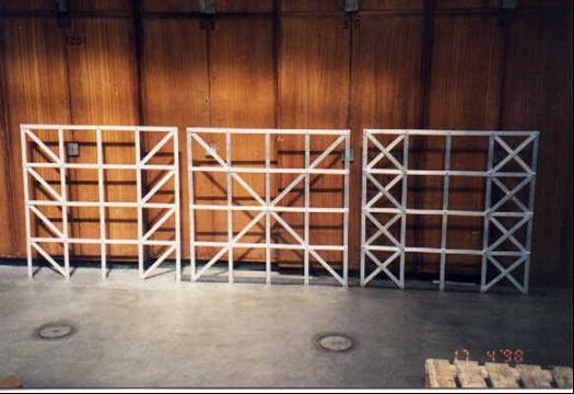
Three aluminium frames were constructed with the same overall dimensions of 1025 mm by 1025 mm. All members of the frames have the same cross-section of 25 mm by 3 mm. The only difference between the three frames is the arrangement of the bracing members as shown in Fig. 8-3. It can be seen from Fig. 8-5 that
a) Frame A is traditionally braced with eight members, which satisfies the first criterion.
b) Eight bracing members are again used in Frame B but are arranged to satisfy the first three criteria.
c) A second traditional bracing pattern is used for Frame C with sixteen bracing members arranged satisfying the first two criteria.
The three frames were tested using a simple arrangement. The frames were fixed at their supports and a hydraulic jack was used to apply a horizontal force at the top right-hand joint of the frame. A micrometer gauge was used to measure the horizontal displacement at the top left-hand joint of the frame. A lateral restraint system was provided to prevent out-of-plane deformations [8.7].
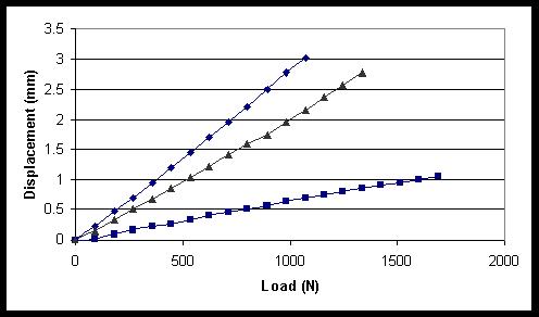
The horizontal load-deflection characteristics of the three frames are shown in Fig. 8-6. It can be seen that the displacements of Frame B, which satisfied the first three criteria, are about a quarter of those of Frame A for the same load. Frame C with eight more members but not satisfying the third criteria is obviously less stiff than Frame B. For example, the displacements corresponding to the load of about 1070N are 3.0mm for Frame A, 0.73mm for Frame B and 2.2mm for Frame C respectively. The experiment results for Frame A and Frame B align with the conclusions obtained in Example 8-1.
Direct and zigzag force paths
This model demonstratio allows one to feel the relative stiffensses of two similar plastic frames and shows the effect of internal force paths.
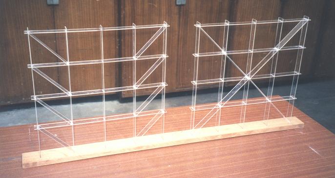
In order to ‘feel’ the effect of the force paths, two frames were made of plastic, with the same overall dimensions 400 mm by 400 mm and member sizes of 25 mm by 2 mm, see Fig. 8-7 [8.7]. The only difference between the two frames is the arrangement of bracing members. The forms of the two frame models are the same as the example calculated in section 8.2.3 and the test Frames A and B in Section 8.3.1. The relative stiffnesses of the two frames can be felt by pushing a top corner joint of each frame horizontally. The frame on the right side feels much stiffer than the one on the left. In fact, the stiffness of the right frame is about four times that of the left frame. The load applied to the right frame is transmitted to its supports through a direct force path while for the frame on the left, the force path is zigzag.
Practical Examples
Bracing systems of tall buildings
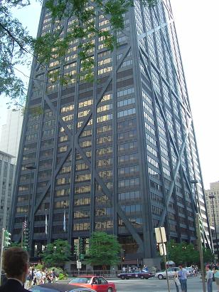
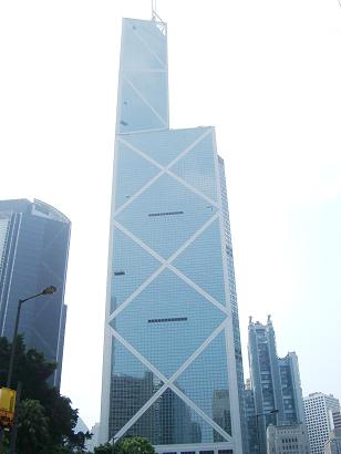
Fig. 8-8: Bracing systems used in buildings satisfying the first three criteria
The 100-storey 344 m tall building, the John Hancock Centre in Chicago, has an exterior-braced frame tube structure. An advance on the steel-framed tube, this design added global cross-bracing to the perimeter frame to increase the stiffness of the structure as shown in Fig. 8-8a. Some $15 million was saved on the conventional steelwork by using these huge cross braces [8.8]. It was regarded as an extremely economical design which achieved the required stiffness to make the building stable. One of the reasons for the success was, as can be seen from Fig. 8-8a, that the required lateral stiffness of the structure was achieved by using the cross-braces resulting in direct force paths and smaller internal forces according to the first concept or the first three criteria (Sections 8.1 and 8.2). The Bank of China, Hong Kong (Fig. 8.8b) also adopts a similar bracing system.
Bracing systems of scaffolding structures
Scaffolding structures are temporary structures that are an essential part of the construction process. Scaffolding imposes certain design restrictions that can be ignored in the design of other structures. For example, scaffolding structures must be easily assembled and taken apart, and the components should also be relatively light to permit construction workers to handle them. Although scaffolding structures are light and temporary in the majority of cases, their design should be taken seriously. The concept of direct force paths and the five criteria are applicable to scaffolding structures.
1. The collapse of a scaffolding structure
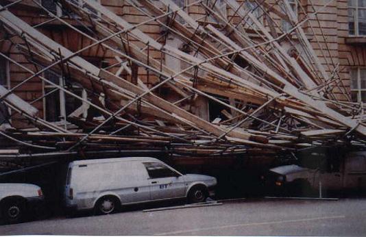
The scaffolding structure shown in Fig. 8-9 collapsed in 1993 [8.9], although no specific explanation was given. Using the concept of direct force paths and the understanding gained from the previous examples, the cause of the incident may be explained. It can be seen that in this scaffolding structure no diagonal (bracing) members were provided, i.e. no direct force paths were provided. The scaffolding structure worked as an unbraced frame structure, and the lateral loads, such as wind loads, on the structure were transmitted to its supports through bending of the slender scaffolding members. The structure did not have enough lateral stiffness and collapsed under wind loads only.
2. Some bracing systems used for scaffolding structures
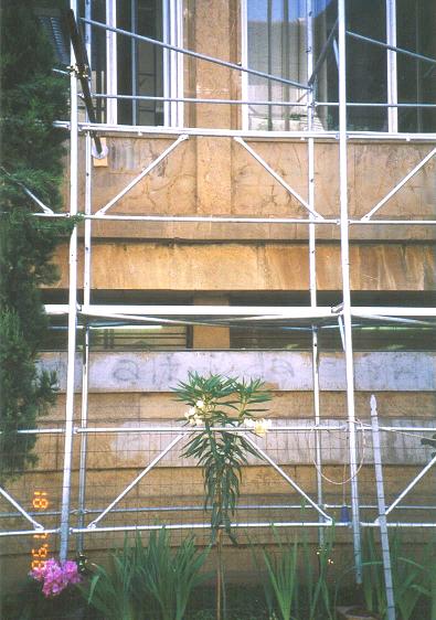
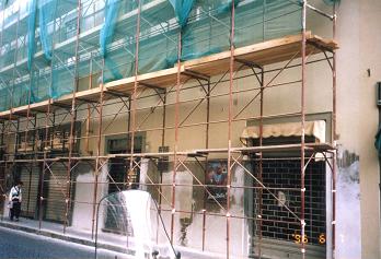
Fig. 8-10: Inefficient bracing systems for scaffolding structures
For the convenience of erection of the scaffolding structures shown in Fig. 8-10, standard units were used. The unit shown in Fig. 8-10a consists of two horizontal members, two vertical members and two short bracing members. The unit is useful for transmitting the vertical loads applied to the top horizontal member to the vertical members that support the unit at its two ends. The unit is equivalent to a thick beam in the structure and the scaffolding structure becomes a deep beam and slender column system. The diagonal members used in the structure do not provide the force paths to transmit the lateral loads on the structure from the top to the bottom of the structure and do not follow the basic criteria for arranging bracing members. Therefore it can be seen that the scaffolding structure has a relatively low lateral stiffness based on the first concept of direct force paths.
Bracing members are also provided in the scaffolding structure shown in Fig. 8-10b. However, these bracing members are linked in the horizontal direction but not connected from the top to the bottom of the structure, and do not create direct force paths. Therefore, without any calculation, it can be judged that the scaffolding structure possesses a relatively low lateral stiffness.
References
8.1 Parker, S. P., (1997), Dictionary of Engineering, 5th Edition, McGraw-Hill, New York, ISBN 0-07-052435-1.
8.2 Gere J M, (2004), Mechanics of Materials, Thomson Books/Cole, USA, ISBN 0-534-41793-0.
8.3 Ji, T, (2003), Concepts for designing stiffer structures, The Structural Engineer, Vol.81, No.21, pp.36-42.
8.4 Ji, T. and Ellis, B. R., (1997), Effective bracing systems for temporary grandstands, The Structural Engineer, Vol.75, No.6, pp.95-100.
8.5 The Structural Engineer, Vol.72, No.3, 1994.
8.6 Lian, Q, Xie, Y and Steven, G, (2000), Optimal topology design of bracing systems for multi-story steel frames, Journal of Structural Engineering, ASCE, Vol. 126, No.7, pp.823-829.
8.7 Roohi, R, (1998), Analysis, testing and model demonstration of efficiency of different bracing arrangements, Investigative Project Report, UMIST.
8.8 Bennett, D, (1995), Skyscrapers – Form & Function, Simon & Schuster, New York, ISBN 0-684-80318-6.
8.9 Anderson, J (1996), Teaching health and safety at university, Proceedings of the Institution of Civil Engineers, Journal of Civil Engineering, Vol.114, No.2, pp.98-99.