Smaller Internal Forces
- The more direct the internal force paths, the stiffer the structure.
- The more uniform the distribution of internal forces, the stiffer the structure.
- The smaller the internal forces, the stiffer the structure.
Smaller internal forces in a structure or a stiffer structure can be achieved by:
- providing additional supports to the structure
- reducing spans of the structure or
- making a self-balanced system of forces in the structure before the forces are transmitted to the supports of the structure.
The first two measures are obvious. The contents of this chapter are related to the third measure.
Criterion:
If members can be added into a structure in a way that offsets some of the effects of the external loads or balances some of the internal forces before the forces are transmitted to the supports of the structure. The internal forces in the structure will be smaller and the structure will be stiffer.
Model Demonstrations
A pair of rubber rings
This pair of models demonstrate that a tied ring is much stiffer than a similar ring without a tie.
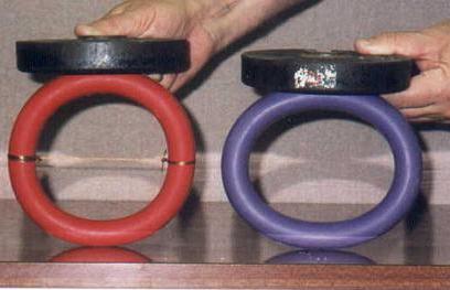
Fig.9-8 shows two rubber rings, one with and one without a wire tied across the diameter. The dimensions and material properties of the rings are described in Example 9-1 where the calculated vertical displacements of the rings are given . The same weight of 22.3 N is placed on the top of each of the two rings and the reduced deformation of the tied ring is apparent and its increased stiffness can be seen and felt. This may be explained since the force in the wire increases as the applied load increases, and produces a bending moment (Eq. 9-10a) in the ring in the opposite direction to the bending moment (Eq. 9-8a) caused by the external load (Fig. 9-2). In this way the force in the wire balances part of the bending moments in the ring, reducing the internal forces in the ring, thus making it stiffer.
Examples of this criterion in practice are tied arches and tied-pitched roofs. The ties help to balance horizontal forces and reduce horizontal displacements, thus effectively increasing the structural stiffness.
Post-tensioned plastic beams
This demonstration shows that a beam with profiled post-tension wires is clearly stiffer than the same beam with straight post-tensioned wires.
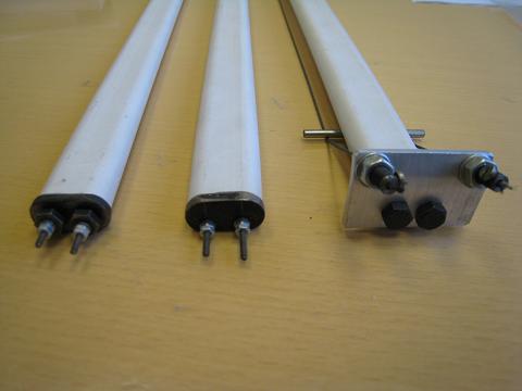
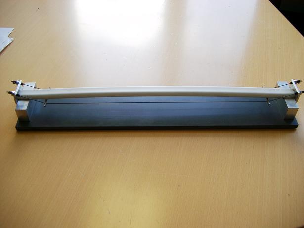
Fig: 9-9: Three post-stressed plastic beams with different positions of wires
Three 500mm long plastic tubes are stiffened by a pair of steel wires whose location differs in each tube, see Fig. 9-9:
Model A: The pair of wires is positioned at the neutral plane of the tube.
Model B: The pair of wires is positioned between the neutral plane and the bottom of the tube.
Model C: The pair of wires is placed externally with a profiled shape rather than being straight. Two small metal bars, longer than the width of the tube, are placed underneath the tube to create the desired profile for the wires.
Small metal plates are placed at the ends of the tubes to provide the supports to fix the wires. The wires are fixed into screws and the screws pass through the holes in the end plates and are fixed using nuts. By turning the nuts, the tension in the wires and the forces in the tubes are established. Fig. 9-9a shows the details of the ends of the three tubes and the locations of the wires. Supporting the beams at their two ends gives three post-tensioned simply supported beams shown in Fig. 9-9b. The structural behaviour of the three model beams can be described as follows:
Model A: As the wires are placed in the neutral plane of the tube, the tube itself is in compression and the wires are in tension.
Model B: As the wires are placed under the neutral plane of the tube, the tube is subjected to both compression and bending (bending upwards) and the wires are in tension.
Model C: As shown in Fig. 9-9b, the tensions in the wires provide upward forces through the two diverters to the beam, which will partly balance the downward loads. In other words, the upward forces are equivalent to two spring supports to the beam. Thus Model C is expected to be significantly stiffer than Models A and B.
Positioning the Models in turn on the supports shown in Fig. 9-9b then pressing at the centre of each beam downwards, it can be felt that Model C is obviously stiffer than the Models A and B. The three models all form self-balanced systems, but only Model C has enlarged bending stiffness. A practical example of a stiffened floor using profiled post-tensioned cables will be given in Section 9.4.4.
Practical Examples
Raleigh Arena
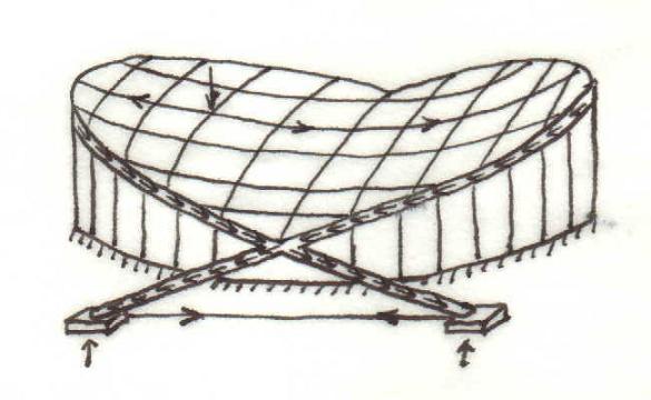
The roof structure of the Raleigh Area (Fig. 9-10) consists of carrying (sagging) cables and stabilising (hogging) cables which are supported by a pair of inclined arches. The structure forms, at least in part, a self-balanced system, which effectively reduces the internal forces in the arches. The carrying cables apply large forces to the arches and some of the vertical components of the forces are transmitted to external columns. Significant portions of the bending moments and the horizontal components of the shear and compressive forces in the arches are self-balancing at the points of contact between the two arches. Most of the horizontal components of the remaining shear and compressive forces in the lower parts of the arches are balanced by underground ties, which have a similar function to the wire tie in the ring used in the demonstration. The reduced internal forces not only allow the use of less material but also lead to a stiffer structure.
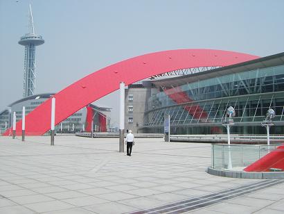
Another example is the newly built stadium in Nanjing, China. The roof of the stadium is supported by a pair of arches, which are inclined outwards symmetrically and do not support each other. Fig. 9-11 shows one of the arches. The pair of arches generates large horizontal forces of 13,000 kN at their supports. In order to avoid these horizontal forces at the ends of the arches being applied to the pile foundations, which are on soft soil, eight post-tension cables of a diameter of 25mm and a length of 400 m are placed underground to link the two ends of each arch to balance the large horizontal forces. The cables have the same functions as demonstrated in the tied rubber ring.
Zhejiang Dragon Sports Centre
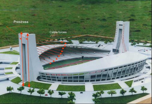
The Zhejiang Dragon Sports Centre in China was built in 2000. The stadium has a diameter of 244m and the cantilever roof spans of 50m, creating unobstructed viewing for the spectators. The roof structure adopts double layer lattice shells that are supported by internal and external ring beams. Cables carry the internal ring beams back to the support towers located at two ends of the stadium. The cables are used as elastic supports to the roof, reducing the internal forces (bending moments) and increasing the stiffness of the shell roof.
The towers are subjected to large forces from the cables, which transmit the weight of the cantilever roof and the loads on the roof to the towers. These forces in turn cause large bending moments in the 85m tall cantilever towers. To reduce the bending moments in the towers, post-tension forces were applied to the backs of the towers providing the bending moments opposing the effects of the cables. In this way, the bending moments in the towers become smaller. This leads to a saving of material and a stiffer structure.
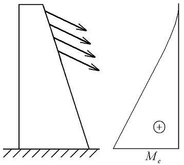
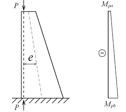
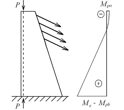
Fig. 9-13: Illustration of the bending moments in a tower of the Zhejiang Dragon Sports Centre
The bending moments in one of the towers are illustrated in Fig. 9-13. Fig.9-13a shows qualitatively the elevation of the tower and the forces applied on the tower together with the bending moments in the tower. The maximum bending moment occurs at the base of the tower and is noted as ![]() . Fig. 9-13b shows the action of the post-tension forces applied on the tower and the corresponding bending moments. As the distance between the vertical line of action of the compression forces and the neutral axis of the tower varies linearly, the bending moment increases linearly from
. Fig. 9-13b shows the action of the post-tension forces applied on the tower and the corresponding bending moments. As the distance between the vertical line of action of the compression forces and the neutral axis of the tower varies linearly, the bending moment increases linearly from ![]() at the top to
at the top to ![]() at the bottom of the tower, in the opposite direction to those induced by the cable forces. Finally Fig. 9-13c gives the combinations of the two sets of forces on the structure and the resulting bending moments. Thus the bending moments due to the combined forces are
at the bottom of the tower, in the opposite direction to those induced by the cable forces. Finally Fig. 9-13c gives the combinations of the two sets of forces on the structure and the resulting bending moments. Thus the bending moments due to the combined forces are ![]() at the top and
at the top and ![]() at the base. The reduced bending moments due to the action of the post-tensioning of the tower is obvious. According to Eq.9-2, the reduced forces will result in smaller displacements, i.e . a stiffer structure.
at the base. The reduced bending moments due to the action of the post-tensioning of the tower is obvious. According to Eq.9-2, the reduced forces will result in smaller displacements, i.e . a stiffer structure.
A cable-stayed bridge
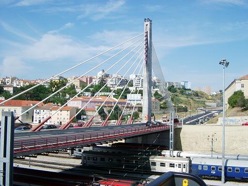
There are many long-span cable-suspended and cable-stayed bridges in the world. Cables are used for the bridges not only because they are light and have high tensile strength, but also because they can create self-balanced systems in the structures and because the cables provide elastic supports to reduce the effective span of the decks. The latter reason is more significant.
Fig. 9-14 shows a cable-stayed bridge in Lisbon. The stayed cables act as elastic supports to the bridge decks, which effectively reduce the internal bending moments in the decks allowing the large clear spans. As the internal forces become smaller, the bridge deck becomes stiffer and can span greater clear distance, producing a more economical design.
This behaviour of the bridge can also be considered using the concept of direct force paths. Due to the use of cables, the loads acting on the bridge decks are not transmitted to their supports primarily through bending actions. Rather, loads are transmitted mainly through the tensile forces in cables to the support tower (Fig. 9-14), with the horizontal components of the cable forces induced by the self-weight of the bridge being self-balanced due to the symmetry of the structure. Vertical components of the cable forces pass directly through the tower to the foundation.
As a partially self-balanced system is created, forces are transmitted in a relatively straightforward manner from the deck to the supports, producing a stiffer and more economical design.
A floor structure experiencing excessive vibration
A floor in a factory on which machines were operated on a daily basis experienced severe vibrations causing significant discomfort for workers. It was found that resonance occurred when the machines operated. The solution to the problem was to avoid the resonance by increasing the stiffness of the floor or its natural frequency.
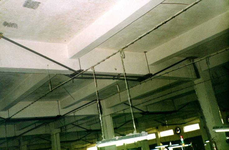
It was not feasible to stiffen the floor by positioning additional column supports. However, the resonance problem was solved in a simple and economical manner by the Institute of Building Structures, China Academy of Building Research, Beijing, through stiffening the floor using external post-tensioned tendons as shown in Fig. 9-15.
Due to the profile of the tendons and the post-tension forces applied, additional upward forces or elastic supports are provided at the points where the steel bars react against the concrete beams which support the floor. This reduces the internal forces (bending moments) in the beams, making the floor system stiffer with increased natural frequencies. With the natural frequencies avoiding the operating frequency of the machine, resonance did not occur and the response of the floor was significantly reduced. The static behaviour of the structure is demonstrated in Section 9.3.2.
References
9.1 Ji, T, (2003), Concepts for designing stiffer structures, The Structural Engineer, Vol.81, No.21, pp.36-42.
9.2 Gere J M, (2004), Mechanics of Materials, Thomson Books/Cole, USA, ISBN 0-534-41793-0
9.3 Seed, G M, (2000), Strength of Materials, Saxe-Coburg Publications, Edinburgh, ISBN 1 874672 12 1.
9.4 Bobrowski, J, (1986), Design philosophy for long spans in buildings and bridges, Journal of Structural Engineer, Vol. 64A, No.1, pp. 5-12.