Bending
For a beam subjected to bending,
- Elongation occurs on one surface and shortening on the opposite surface of the beam. There is a (neutral) plane through the beam which does not change in length during bending.
- Plane cross sections of the beam remain plane and perpendicular to the neutral axis of the beam.
- Any deformation of a cross section of the beam within its own plane is neglected.
- The normal stress on a cross-section of the beam is distributed linearly with the maximum normal stresses occuring on surfaces farthest from the neutral plane.
Model Demonstrations
Assumptions in beam bending
This demonstration examines some of the basic assumptions used in the theory of beam bending.
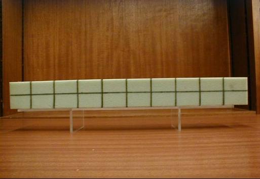
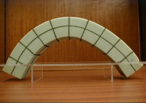
Fig. 4-4: Examination of beam bending assumptions
A symmetric sponge beam model is made which can be bent and twisted easily (Fig. 4-4a). Horizontal lines on the two vertical sides of the beam are drawn at mid-depth, indicating the neutral plane and vertical lines at equal intervals along the length of the sponge are made indicating the different cross sections of the beam.
Bending the beam as shown in Fig. 4-4b, it can be observed that:
- all of the vertical lines, which indicate what is happening to the cross sections of the beam, remain straight;
- the angles between the vertical lines and the centroidal line (neutral axis) remain at 90 degrees;
- the upper surface of the beam extends and the bottom surface shortens;
- the length of the centroidal (neutral) axis of the beam does not change.
A thin beam and a thick beam
This demonstration shows that the assumptions used to study the bending of a thin beam do not hold for a thick beam for which significant shear deformation occurs.
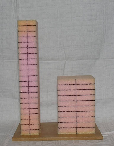
Figure 4.A1: Thin and Thick sponge beams
Figure 4.A1 shows two sponge beams that have square cross-sections but have different length to width ratios. The beams are set up as vertical cantilevers to be acted upon by transverse loads. The loads will cause bending and shear stresses and deformations throughout the beams. To make these phenomena visible, both beams are marked by several horizontal lines, indicating the transverse cross-sections, as well as vertical lines indicating the neutral axes.
The thin beam on the left has a length to width ratio about 6:1. When a transverse load is applied at the free end of the beam, it can be seen in Figure 4.A2a that plane sections remain plane and normal to the neutral axis even with the large deformations.
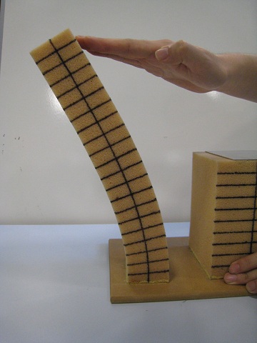
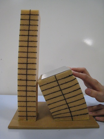
Deformation of the Thick beamFigure 4.A2: Deformations of the Thin and Thick beams
The thick beam on the right has a length to width ratio about 3:2. In this case the effect of shear deformation cannot be neglected. Applying the transverse force to the top of the beam causes warping of the horizontal lines that are no longer straight and perpendicular to the neutral axis (Figure 4.A2b). This phenomenon indicates that the stresses are no longer linearly distributed along the cross-sections of the beam. The behavior of thin beams and thick beams in bending is different and the equations derived for thin beams do not apply to thick beams.
Practical Examples
Profiles of girders
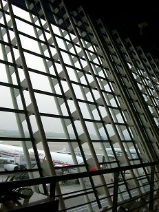
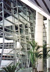
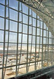
Fig. 4-5: A series of girders supporting windows at airport terminals
Large curtain or window walls are often seen at airport terminals. Fig. 4-5 shows three such walls. These large window walls are supported by a series of plane girders. The wind loads applied on the window walls are transmitted to the girders and through the girders to their supports.
The girders act like vertical simply supported “beams”. The bending moments in the “beams” induced by wind loads are maxima at or close to their centres and minima at their ends. If the wind load is uniformly distributed, the diagrams of bending moments along the “beams” will be parabolas. Thus it is reasonable to design the girders to have their largest depths at their centres and their smallest depths at their ends with the profiles of the girders being parabolas. The girders shown in Fig. 4-5c reflect this and appear more elegant than those shown in Figs. 4-5a and 4-5b.
Reducing bending moments using overhangs
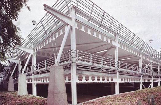
Fig. 4-6: Overhangs used to reduce bending moments and deflections (courtesy of Mr. J Calverley)
Fig. 4-6 shows a steel-framed multi-storey carpark where cellular beams are used. The vertical loads from floors are transmitted to the beams and then from the beams through bending to the supporting columns. Overhangs are used in the structure which can reduce the bending moments and deflections of the beams. Examining the first overhang, two steel wires are placed to link the free end of the overhang and the concrete support. A downward force on the free end of the overhang is provided by tensions induced in the pair of steel wires. This force will generate a negative bending moment over the column support which will partly off-set the positive moments induced in the beam by applied loading.
Failure due to bending
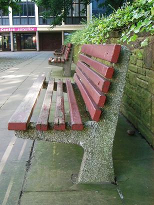
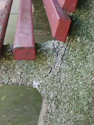
Fig. 4-7: A bench with cracks
Fig. 4-7a shows a bench which consists of wooden strips, serving as seating and backing, and a pair of concrete frames supporting the seating and backing. Fig. 4-7b shows cracks at the end of the cantilever of one of the concrete frames. The two main cracks in the upper part of the cantilever (Fig. 4-7b) are a consequence of the normal stresses induced by bending exceeding the limit stress of concrete.
Deformation of a staple due to bending
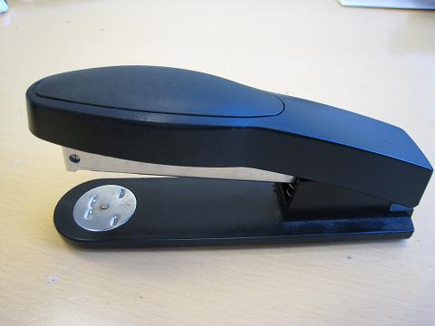

Fig. 4-8: A typical stapler
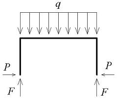
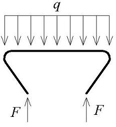
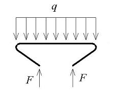
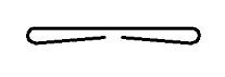
Fig. 4-9: The process of the deformation of a staple
Staplers are common sights in offices. Fig. 4-8 shows a typical stapler which creates closed staples through a process of bending and plastic deformation. In this case it can be seen that the two symmetric indents or grooves in the front part of the base of the stapler have bowed shapes.
Fig. 4-9 shows the process of the deformation of a staple by the stapler. Initially a staple looks like a frame structure without supports at the two ends of the two vertical elements. When the stapler is depressed, distributed loads are applied on the horizontal element (the middle part of the frame) and these loads push the staple through the multiple sheets of paper being joined to meet the metal base of the stapler. When the staple reaches and enters the grooves in the base, both vertical and lateral forces are applied to the ends of the staple as shown in Fig. 4-9a. The lateral forces, which are induced due to the shape of the grooves, make the two vertical elements of the staple bend and move inwards. When the staple reaches the position shown in Fig. 4-9b, the ends of the staple leave the grooves and no lateral forces act. In this position the vertical forces are sufficient to continue to bend the two vertical elements further (Fig. 4-9c). Finally, the staple reaches the shape shown in Fig. 4-9d. The large deformations induced are plastic and permanent.
References
4.1 Hibbeler, R C, (2005), Mechanics of Materials, Sixth Edition, Prentice-Hall Inc, Sigapore, ISBN 0-13-186-638-9.
4.2 Williams M S and Todd J D, (2000), Structures – theory and analysis, Macmillan Press Ltd, London, ISBN 0-333-67760-9.
4.3 Gere J M, (2004), Mechanics of Materials, Thomson Books/Cole, USA, ISBN 0-534-41793-0.