Shear and Torsion
Shear: A force (or stress) which tends to slide the material on one side of a surface relative to the material on the other side of the surface in directions parallel to the surface is termed a shear force (or shear stress).
Torsion: A moment that is applied about the longitudinal axis of a member is called a torque which tends to twist the member about this axis and is said to cause torsion of the member.
For a circular shaft or a closed circular section member subjected to torsion:
- Plane circular cross sections remain plane and the cross sections at the ends of the member remain flat.
- The length and the radius of the member remain unchanged.
- Plane circular cross sections remain perpendicular to the longitudinal axis.
For a non-circular section member or an open section member subjected to torsion:
- Plane cross sections of the member do not remain plane and the cross sections distort in a manner which is called warping. In other words, the fibers in the longitudinal direction deform unequally.
Model Demonstrations
Effect of torsion
This demonstration shows the effect of shear stress in a non-circular section member induced by torsion.
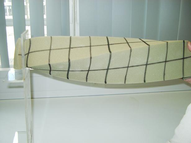
Take a length of sponge of rectangular cross section and mark longitudinal lines down the centre of each face. Then add perpendicular lines at regular intervals along the length of the sponge. Restrain one end of the sponge in a plastic frame as shown in Fig. 5.5 and twist the other end. It can be observed that:
- The lines defining the cross sections of the beam are no longer straight.
- The angles between the horizontal longitudinal lines, which define the neutral axis, and the vertical lines are no longer 90 degrees.
These observations are different from those of the beam in bending, see Section 4.3.1.
Effect of shear stress
This demonstration shows the existence of shear stress in bending and how shear resistance/stresses between beams/plates/sheets can significantly increase the bending stiffness of a beam.
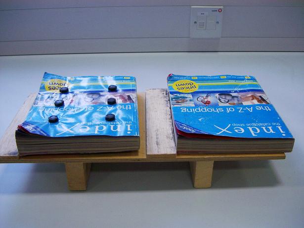
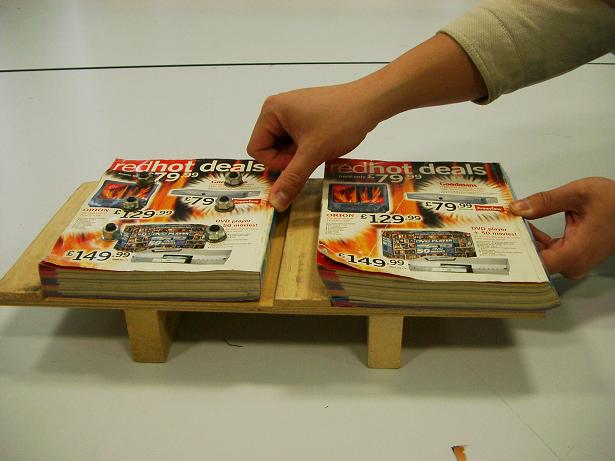
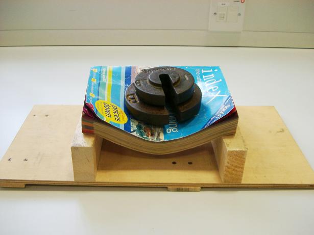
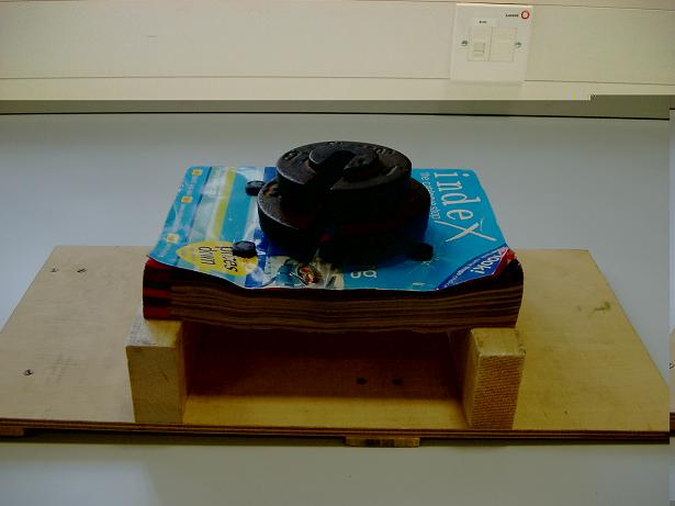
Fig. 5-6: Effect of shear stress in catalogues
Take two identical thick catalogues and drill holes through one of them and then put bolts through the holes and tighten the bolts as shown in Fig. 5-6a. Place the two catalogues on a wooden board up against two wood strips, say a quarter the thickness of a catalogue, which are secured to the board and apply a horizontal force at the top right edge of each of the two catalogues as shown in Fig. 5-6b. It is apparent that the thin pages slide over each other in the unbolted catalogue while in the bolted catalogue there is no movement of the pages. This is because the bolts and the friction between the pages provide horizontal shear resistance and prevent the pages sliding between each other.
Support the two catalogues at their ends on two wooden blocks on the board as shown in Figs. 5-6c and 5-6d and place the same weight at the mid-span of each of the two catalogues. Fig. 5-6c and 5-6d show the bending deflections of the two catalogues with the unbolted catalogue experiencing large deformations while the bolted catalogue experiences only small deformations. The bolts and the friction between the pages provide horizontal shear resistance between the pages of the bolted catalogue and make this act as a single member, a ‘thick’ beam or plate, whereas in the unbolted catalogue the pages act as a series of very ‘thin’ beams or plates.
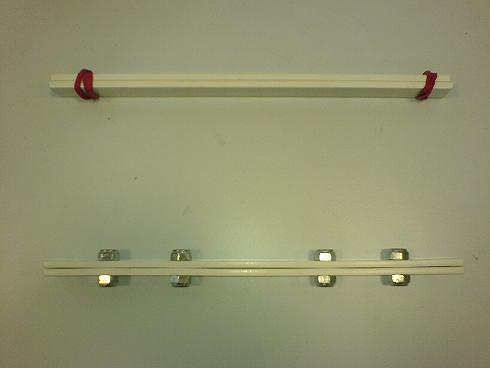
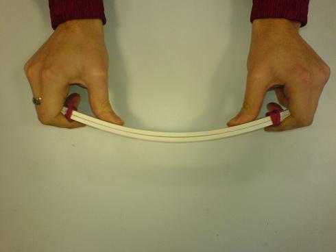
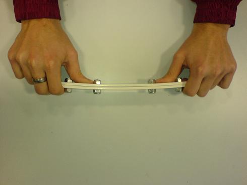
Fig. 5-7: Effect of shear resistance in beams
A similar but simpler demonstration of the effect of shear stress can be demonstrated using beams made up of two strips of plastic as shown in Fig. 5-7a. For one beam the two plastic strips are loosely bound with elastic bands and for the other beam the two plastic strips are securely held together with four bolts that act as shear connectors and, because of the tension in the tightened bolts, provide compressive forces on the two strips. Suitable sizes for the strips would be 300mm long, 25mm wide and 10mm thick.
By applying similar forces to the ends of the beams one can observe and feel the effect of the shear connection. When bending the beam without shear connectors, one can see the two strips rub against each other and slightly move relative to one another. This becomes noticeable at the ends of the strips as there is little shear resistance between the two strips. When bending the beam with shear connectors, one can feel that the beam is much stiffer than the beam without shear connectors and it is possible to see that there is no relative movement between the strips.
Effect of shear force
This demonstration shows how lateral forces can be resisted and transmitted in frame structures through the use of shear elements, such as shear walls.
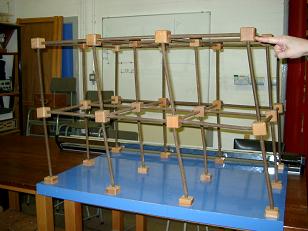
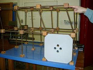
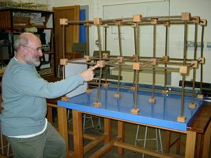
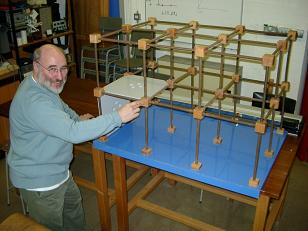
Fig. 5-8: Effect of shear walls
(The demonstration model was provided by Mr. P Palmer, University of Brighton)
Fig. 5-8a shows a three-dimensional frame system in which the columns and beams are made of steel springs with wooden joints linking the beams and columns. Applying a horizontal force to the top corner of the frame causes the frame to move in the direction of loading. It can be seen from Fig. 5-8a that the angles between beams and columns are no longer 90 degrees as was the case in the unloaded frame.
If a wooden board is fitted into a lower vertical panel of the frame as shown in Fig. 5-8b and the same force is applied as was the case in the last demonstration, it is observed that the upper story experiences horizontal or shear deformations while the lower storey is almost unmoved. The wood panel acts as a shear wall which has a large in-plane stiffness enabling it to transmit horizontal loads in the lower storey directly to the frame supports.
If the wooden board is replaced in a vertical plane in the lower part of one of the end frames as shown in Fig. 5-8c and a force is applied at the joint which is one bay away from the wooden board, it is observed that the frame to which the force is applied deforms significantly and the frame where the wooden board is placed has little movement.
If a further wooden board is placed in a horizontal plane, at first storey level, next to the vertical board as shown in Fig. 5-8d and a force is applied at the joint at the corner of the horizontal panel, it can be seen that there is little movement at the point where the force is applied. This is because the horizontal and vertical panels have large stiffnesses in their planes and the shear force is transmitted directly through the wooden boards to the supports.
Open and closed sections subject to torsion with warping
This demonstration shows the difference in the torsional stiffness of two circular members, one with a closed section and the other with an open section where warping can be observed.
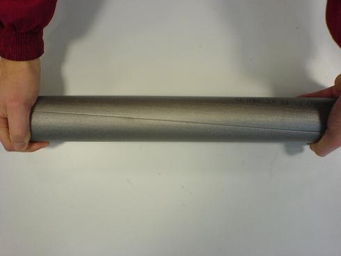
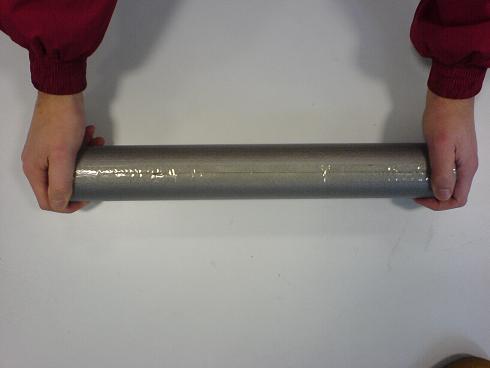
Fig. 5-9: Open and closed sections subject to torsion with warping
Fig. 5-9 shows two foam pipes that are used for insulation and each of the two pipes has a length of 450 mm. The sections have machined slits and in one of the pipes the slit is sealed using tape and glue. One pipe thus effectively has an open circular section and one has a closed circular section. The sections have been analysed in Example 5-2 where it was predicted that the torsional stiffness of the closed section was 3.5 times that of the open section. By twisting the two foam pipes it is possible to feel the significant difference in their torsional stiffnesses.
When twisting the two foam pipes with a similar effort it can be seen from Fig. 5-9 that:
- It is much easier to twist the open section than the closed section.
- The effect of warping can be observed (Fig. 5-9a) at the right hand end of the pipe which has a slit along its length.
- There is little warping effect on the pipe with the closed section (Fig. 5-9b).
Open and closed sections subject to torsion without warping
This demonstration shows the difference in the torsional stiffness of two non-circular members, one with a closed section and the other with an open section where warping is restrained.
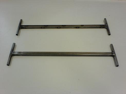
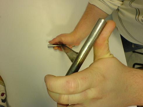
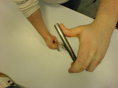
Fig. 5-10: Open and Closed sections subjected to torsion without warping
Fig. 5-10a shows two 500mm long steel bars, one with a square hollow section and the other with an I section which is made by cutting a square hollow section into two halves along its length and welding the resultant channel sections back to back. Handles are welded to the ends of the bars to allow end torques to be easily applied. The sections have been analysed in Example 5-3. Due to the addition of the handles, the warping that occurs in open sections as shown in Section 5.3.4 is now restrained. In other words, the model with the I section would be stiffer than that analysed in Example 5-3.
By applying torques at the ends of the two bars it is readily felt that the bar with a closed section is much stiffer than that the bar which has an open section.
Shear centre of a thin-walled open section
This demonstration shows the location of the shear centre of a thin-walled open section. When a vertical force is applied through the shear centre of the section, no twisting or torsion occurs.

Figure 5.A1: Different loading positions of three identical cantilever beams with open sections
Figure 5.A1 shows three identical plastic beams with channel cross sections. The shear centre of a cross-section can be identified by the definition of the shear centre. A different loading position for each beam is selected. From left to right, the loading positions are to the left of the shear centre, at the shear centre and to the right of the shear centre. Loads can be applied by pulling bronze wires attached to the loading points.
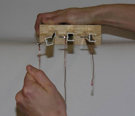
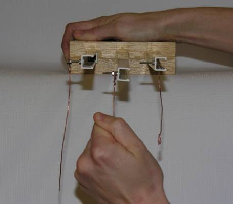
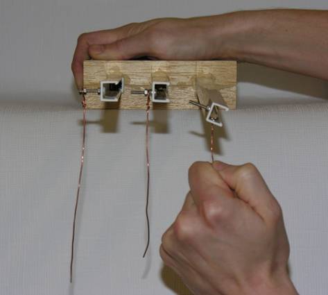
Figure 5.A2: Deformation of the beams due to vertical loads
Figure 5.A2 shows the responses of the three cantilevers to the applied loads. It can be observed from Figure 5.A2 that:
- The beam is twisted in the anti-clockwise direction when the load is applied to the left of the shear centre.
- The beam deforms vertically without twisting when the load is applied through the shear centre of the section.
- The beam is twisted in the clockwise direction when the load is applied to the right of the shear centre.
Practical Examples
Composite section of a beam
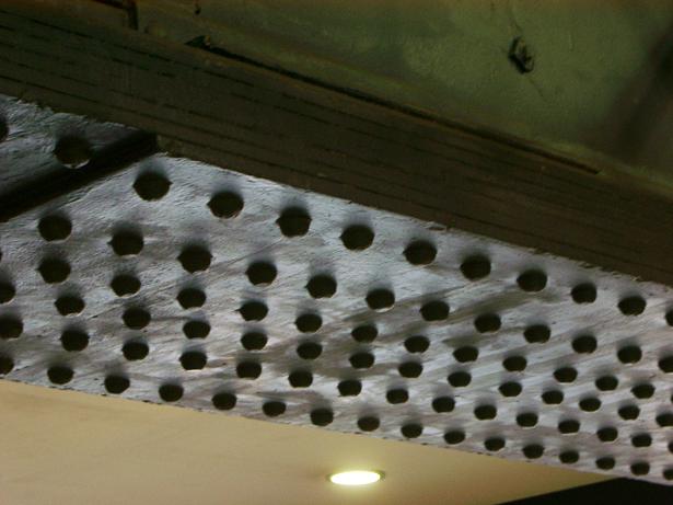
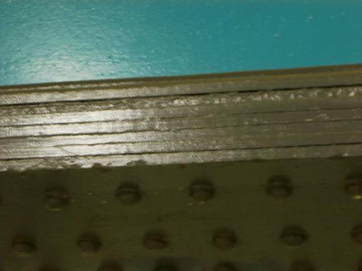
Fig. 5-11: composite sections
Fig. 5-11 shows a number of steel plates or thin beams which are bolted together to form a thick beam. As demonstrated in Section 5.3.2, due to the action of the bolts, there are no relative sliding movements between the thin plates/beams when the beam is loaded and due to the shear resistance of the connecting bolts, the thin plates/beams act together as a single member, which is many times stiffer than that a member which would result from the plates/beams acting independently.
Shear walls in a building
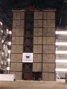
Fig. 5-12: Shear walls in a steel framed building
Shear walls and bracing members are often present in buildings to provide lateral stiffness and to transmit lateral loads, such as wind loads, to the foundations of the buildings. Fig. 5-12 shows one end of a steel framed building where masonry walls and bracing members are used from the bottom to the top of the building to increase the lateral stiffness of the frame structure.
The dynamic behaviour of this building has been examined, experimentally and numerically, at five distinct construction stages, including the building with and without the walls [5.5]. The walls and bracing members contributed significant stiffness to the building which was reflected in the natural frequencies and their associated mode shapes. The walls and bracing members in the ends of the building increased the fundamental transverse natural frequency from 0.72Hz for the bare frame structure to 1.95Hz for the braced structure. The walls in the other two sides of the building were only one quarter storey height and they increased the fundamental natural frequency from 0.71Hz to 0.89Hz.
Opening a drinks bottle
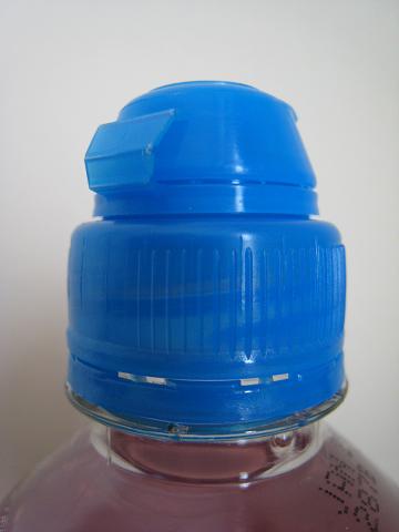
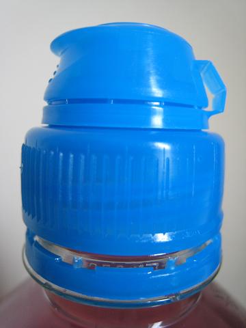
Fig. 5-13: Opening of a drinks bottle
When opening the lid of a common plastic drinks bottle, a torque T applied to the cap is gradually increased until the plastic connectors between the cap and the bottle experience shear failure.
Fig. 5-13a shows the connectors which keep the bottle sealed. If there are n connectors, each with an area A, uniformly distributed along the circumference of the cap which has a radius of r and the failure shear stress of the plastic connectors is , the equation of torsional equilibrium for the cap before being opened is . To open the bottle, the failure shear stress has to be reached and the design of the cap and its connection to the bottle, in terms of the size of the cap and the number and size of the connectors, needs to be such that this can be achieved with a modest effort. Fig. 5-13b shows the shear failure of the connectors.
A box girder highway bridge
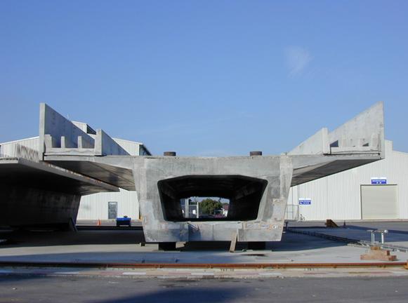
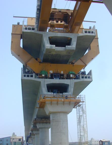
Figure 5.14: A closed box section for a highway bridge (Courtesy of Mr B Duguid, Mott MacDonald)
Figure 5.14 shows the so-called box girder bridge in which the main beams are girders with the shape of a hollow box. The box girder shown in Figure 5.14 is trapezoidal in cross-section but rectangular shapes of girders are also common.
One of the main advantages of box girders over I section beams is that they provide much improved resistance to torsion than I sectioned beams. As shown in Model 5 in the Model Demonstration section of the chapter, an enclosed section has much higher torsional rigidity than an open section with the same shape and area. As a bridge is often subjected to non-symmetric loads, such as traffic on one side of the bridge, this leads to both bending and torsion actions on the bridge deck. Torsion effects are also more significant when a bridge curves in plan. In addition, the presence of two webs allows wider and hence stronger flanges to be used, allowing longer spans.
References
5.1 Gere J M, (2004), Mechanics of Materials, Thomson Books/Cole, USA, ISBN 0-534-41793-0
5.2 Benham, P P, Crawford, R J and Armstrong, C G, (1998), Mechanics of Engineering Materials, Addison Wesley Longman Limited, Harlow, ISBN 0-582-25164-8.
5.3 Williams M S and Todd J D, (2000), Structures – theory and analysis, Macmillan Press Ltd, London, ISBN 0-333-67760-9.
5.4 Millais, M, (2005), Building Structures – From Concepts to Design, Spon Press, Abington, ISNB 0-415-33623-6.
5.5 Ellis, B. R. and Ji, T., (1996), Dynamic testing and numerical modelling of the Cardington steel framed building from construction to completion, The Structural Engineer, Vol.74, No.11, pp.186-192.