The centre of gravity of a body is the point about which the body is balanced or the point through which the weight of the body acts.
The location of the centre of gravity of a body coincides with the centre of mass of the body when the dimensions of the body are much smaller than those of the earth.
When the density of a body is uniform throughout, the centre of mass and the centroid of the body are at the same point.
If the centre of mass of a body is not positioned above the area over which it is supported, the body will topple over.
The lower the centre of mass of a body, the more stable the body.
Model Demonstrations
Centre of mass of a piece of cardboard of arbitrary shape
This demonstration shows how the centre of mass of a body with arbitrary shape can be determined experimentally.
(a)
(b)
(c)
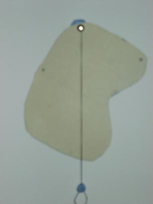
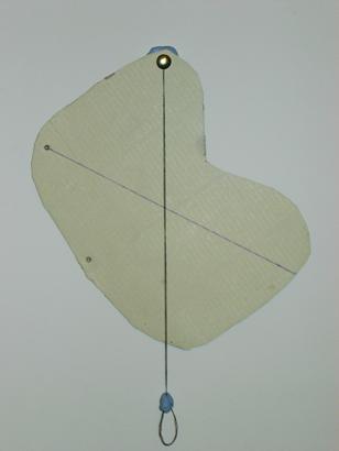
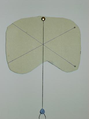
Fig. 2-5: Locating the centre of mass of a piece of cardboard of arbitrary shape
Take a piece of cardboard of any size and shape, such as the one shown in (Fig. 2-5), and drill three small holes at arbitrary locations along its edge. Now suspend the cardboard using a drawing pin through one of the holes and hang from the drawing pin a length of string supporting a weight. As the diameter of the hole is larger than the diameter of the pin, the cardboard can rotate around the pin and will be in equilibrium under the action of the self-weight of the cardboard. This means that the resultant of the gravitational force on the cardboard must pass through the pin. In other words, the action force (gravitational force) and the reaction force from the pin must be in a vertical line which is shown by the string. Now mark a point on the cardboard under the string and draw a straight line between this point and the hole from which the cardboard is supported. Repeat the procedure hanging the cardboard from each of the other two holes in turn and in each case draw a line between a point on the string and the support hole. It can be seen that the three lines (or their extensions) are concurrent at a single point, which is the centre of mass of the piece of cardboard and of course is also the centre of gravity and the centroid of the cardboard.
Centre of mass and centroid of a body
This model is designed to show that the location of the centre of mass of a body can be different from that of the centroid of the body.
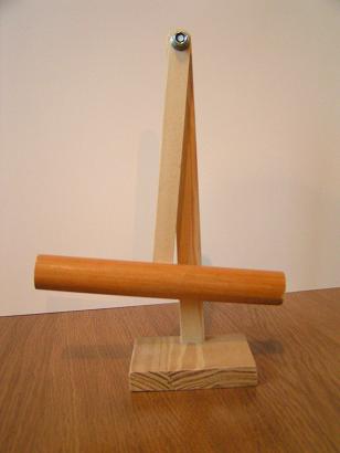
Fig. 2-6: Centre of mass and centroid
A 300mm tall pendulum model is made of wood. The model consists of a supporting base, a mast fixed at the base and a pendulum pinned at the other end of the mast as shown in Fig. 2-6. A metal piece is inserted into the right arm of the pendulum. The centre of mass of the pendulum must lie on a vertical line passing through the pinned point. The centroid of the pendulum lies on the intersection of the vertical and horizontal members. Due to the different densities of wood and metal, the centroid of the pendulum does not coincide with the centre of mass of the body.
Centre of mass of a body in a horizontal plane
This demonstration shows how to locate the centre of mass of a horizontal L shaped body.
(a)
(b)
(c)
(d)
(e)
(f)
Fig. 2-7: Centre of mass of an L-shape body in a horizontal plan
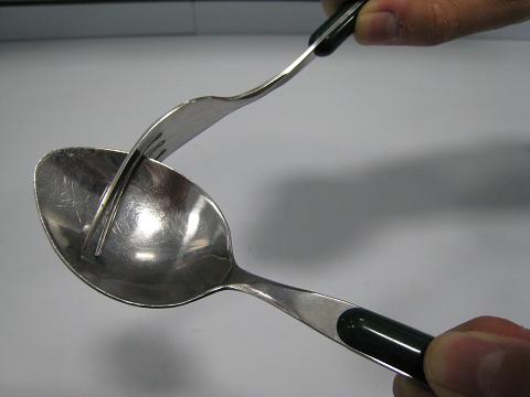
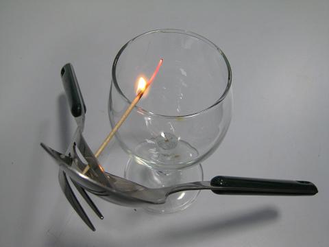
Figure 2-2b shows an L-shaped area whose centre of mass C is outside the body. The following simple experiment, using a fork, a spoon, a toothpick and a wine glass, can be carried out to locate the centre of mass of an L shaped body made up from a spoon and fork.
Take a spoon and a fork and insert the spoon into the prongs of the fork, to form an L-shape as shown in Fig. 2-7a.
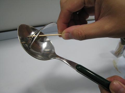
Then take a toothpick and wedge the toothpick between two prongs of the fork and rest the head of the toothpick on the spoon as shown in Fig. 2-7b. Make sure the end of the toothpick is firmly in contact with the spoon.
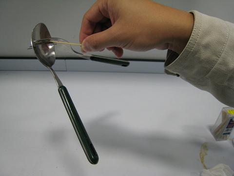
The spoon-fork can then be lifted using the toothpick. The toothpick is subjected to an upward force from the spoon, a downward force from the prong of the fork and forces at the point at which it is lifted as shown in Fig. 2-7c.
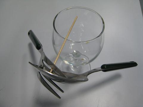
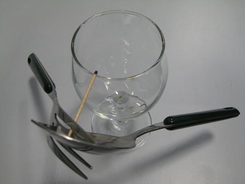
Place the toothpick on to the edge of a wine glass adjusting its position until the spoon-fork-toothpick is balanced at the edge of the glass as shown in Fig. 2-7d. According to the definition of the centre of mass, the contact point between the edge of the glass and the toothpick is the centre of mass of the spoon-fork-toothpick system. The mass of the toothpick is negligible in comparison to that of the spoon-fork, so the contact point can be considered to be the centre of mass of the L-shaped spoon-fork system.
To reinforce the demonstration, set alight the free end of the toothpick (Fig. 2-7e). The flame goes out when it reaches the edge of the glass as the glass absorbs heat. As shown in Fig. 2-7f, the spoon-fork just balances on the edge of the glass.
If the spoon and fork are made using the same material, the centre of mass and the centroid of the spoon-fork system will coincide.
Centre of mass of a body in a vertical plane
This demonstration shows that the lower the centre of mass of a body, the more stable the body.
(a)
(b)
(c)
Fig. 2-8: Centre of mass of a body in a vertical plane
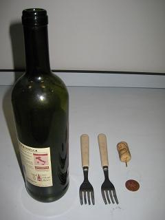
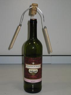
A cork, two forks, a toothpick, a coin and a wine bottle are used in the demonstration shown in Fig. 2-8a. The procedure for the demonstration is as follows:
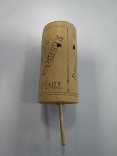
Push a toothpick into one end of the cork to make a toothpick-cork system as shown in Fig. 2-8b.
Try to make the system stand up with the toothpick in contact with the surface of a table. In practice this is not possible as the centre of mass of the system is high and easily falls outside the area of the support point. The weight of the toothpick-cork and the reaction from the surface of the table that supports the toothpick-cork are not in the same vertical line and this causes overturning of the system.
Push two forks into opposite sides of the cork and place the coin on the top of the bottle.
Place the toothpick-cork-fork system on the top of the coin on which the toothpick will stand in equilibrium as shown in Fig. 2-8c.
The addition of the two forks significantly lowers the centre of mass of the toothpick-cork system in the vertical plane below the contact point of the toothpick on the coin. When the toothpick-cork-fork system is placed on the coin at the top of the bottle, the system rotates until the action and reaction forces at the contact point of the toothpick are in the same line, producing an equilibrium configuration.
Centre of mass and stability
This demonstration shows how the stability of a body relates to the location of its centre of mass and the size of its base.
(a)
(b)
(c)
(d)
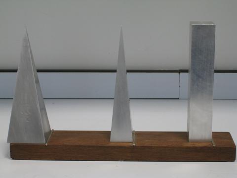
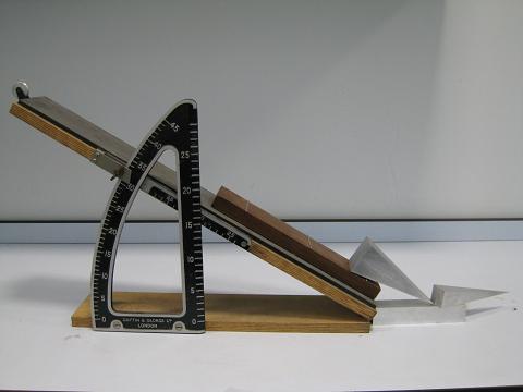
Fig. 2-9: Centre of mass and stability of three aluminum blocks
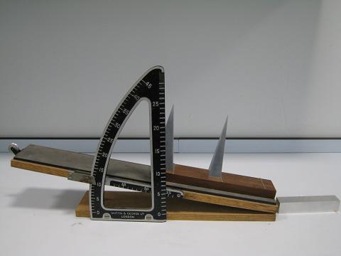
Fig. 2-9a shows three aluminum blocks with the same height of 150mm. The square sectioned block and the smaller pyramid have the same base area of 29mm x 29mm. The larger pyramid has a base area of 50mm x 50mm but has the same volume as that of the square sectioned block. The three blocks are placed on a board with metal stoppers provided to prevent sliding between the base of the blocks and the board when the board is inclined. As the board is inclined, its angle of inclination can be measured by the simple equipment shown in Fig. 2-9b. Basic data for the three blocks and the theoretical critical angles calculated using Eq. 2-7 are given in Table 2-1. Theory predicts that the largest critical angle occurs with the large pyramid and the smallest critical angle occurs with the square sectioned block.
The demonstration is as follows:
The blocks are placed on the board as shown in Fig. 2-9 in the order of increasing predicted critical angle.
The left hand end of the board is gradually lifted and the square sectioned block is the first to become unstable and topple over (Fig. 2-9b). The angle at which the block topples over is noted.
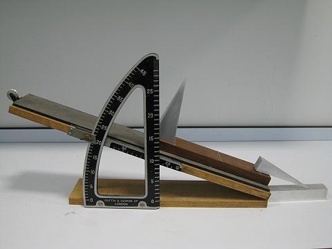
The board is inclined further and the pyramid with the smaller base is the next to topple (Fig. 2-9c). Although the height of the centre of mass of the two pyramids is the same, the smaller pyramid has a smaller base and the line of action of its weight lies outside the base at a lower inclination than is the case for the larger pyramid. The angle at which the smaller pyramid topples over is noted.
As the board is inclined further the larger pyramid will eventually topple over but its improved stability over the other two blocks is apparent (Fig. 2-9d). Once again the angle at which the block topples is noted.
The angles at which the three blocks toppled are shown in Table 2.1.
Table 2.1 Comparison of the calculated and measured critical angles
Model
Cuboid
Small Pyramid
Large Pyramid
Height of the model (mm)
150
150
150
Height of the centre of mass (mm)
75.0
37.5
37.5
Width of the base (mm)
29
29
50
Volume ( )
Theoretical Max Inclination (deg.)
10.9
21.9
33.7
Measured Max Inclination (deg.)
10.0
19.0
31.0
The results of the demonstration as given in Table 2.1 show that:
The order in which the blocks topple is as predicted by Equation 2.7 in terms of the measured inclinations and confirms that the larger the base or the lower the centre of mass of a block, the larger the critical angle that is needed to cause the block to topple.
All the measured critical angles are slightly smaller than those predicted by Eq. 2-7.
Repeating the experiment several times confirms the measurements and it can be observed that the bases of the blocks just leave the supporting surface immediately before they topple, which makes the centres of the masses move outwards. In the theory the bases of the blocks remain in contact with the support surface before they topple.
This demonstration shows that the larger the base and/or the lower the centre of gravity, the larger will be the critical angle needed to cause the block to topple and that this angle is slightly less than that predicted by theory.
Centre of mass and motion
This demonstration shows that a body can appear to move up a slope unaided.
(a)
(b)
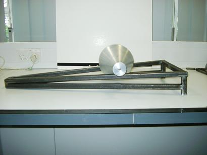
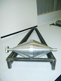
Fig. 2-10: Centre of mass and motion
Take two support rails which incline in both the vertical and horizontal planes as shown in Fig. 2-10. When a doubly conical solid body is placed on the lower ends of the rails, it can be observed that the body rotates and travels up to the higher end of the rails (Fig. 2-10b).
It appears that the body moves against gravity though in fact it moves with gravity. When the locations of the centre of mass of the body, C, are measured at the lowest and highest ends of the rails, it is found that the centre of mass of the body at the lower end is actually higher than that when the body is at the highest end of the rails. It is thus gravity that makes the body rotate and appear to move up the slope.
The reason for this lies in the design parameters of the rail supports and the conical body. The control condition is that the slope of the conical solid body should be larger than the ratio of the increased height to a half of the increased width of the rails between the two ends.
Centre of mass and centre of curvature
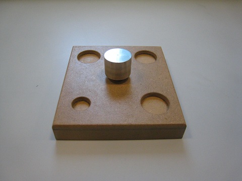
This demonstration shows the relationships between the three states of equilibrium and three relative locations of the centres of mass to the centres of curvature of bodies.
(a)
(b)
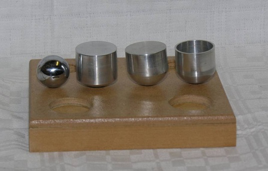
Figure 2.A1: The models
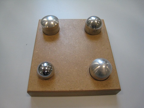
Figure 2.A1 shows four small aluminum axially symmetric objects that have different dimensions and different relative locations of their centres of mass to the centres of curvature (The centre of curvature of a curve at any point is the centre of the circle which is tangent line at the point on the curve. If a line is drawn perpendicular to the curve at the point, the intersection point of the line and the vertical axis of symmetry is the centre of curvature):
a. A round ball: The centre of mass and the centre of curvature of the ball are at the same point, the centre of the ball.
b. A circular solid cylinder attached to a small part of a solid sphere: The centre of mass of the object is lower than the centre of curvature at any point on the spherical surface.
c. A circular solid cylinder attached to a half of a solid sphere: The centre of mass of the object is higher than the centre of curvature at any point on the spherical surface.
d. A hollow circular cylinder attached to a small part of a solid sphere: The centre of mass of the object is lower than the centre of curvature at any point on the spherical surface.
An experiment may be conducted as follows:
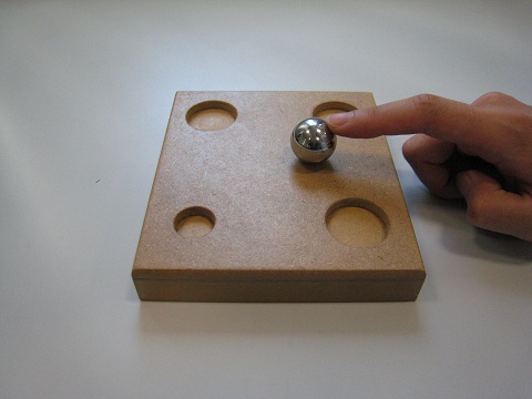
a. Applying a small lateral force on the ball causes it move from its original equilibrium position (Figure 2.A2a). It moves to a new position and a new state of equilibrium (Figure 2.A2b). The original state of equilibrium is a position of neutral equilibrium.
a. Initial position of the ball
b. New position of the ball
Figure 2.A2: Neutral equilibrium
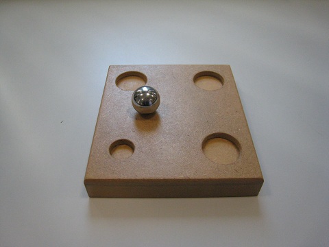
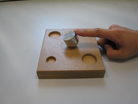
b. Applying a lateral force on the top of the object (b) rotates the object as shown in Figure 2.A3a. Releasing the force, the object returns to its original equilibrium position (Figure 2A3b). The original state of equilibrium is a position of stable equilibrium.
a. Object (b) with applied lateral force
b. Object (b) returns to its original position
Figure 2.A3: Stable equilibrium
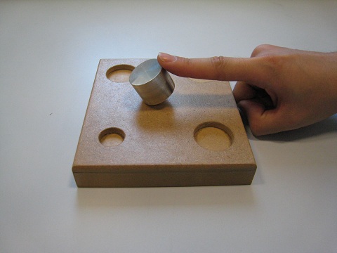
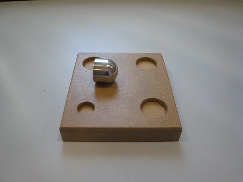
c. Allying a force on the top as above but object (c) of the third object and holding it to the position from its original equilibrium position as shown in Figure 2.A4a. When the finger is removed the object falls over as shown in Figure 2.A4b. This original state of equilibrium is a position of unstable equilibrium.
a. Object (c) with applied lateral force
b. Object (b) Object (c) topples over
Figure 2.A4: Unstable equilibrium
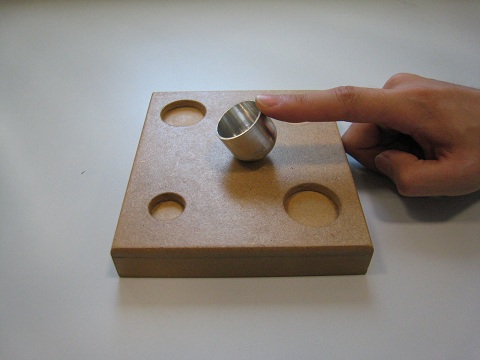
d. Applying a lateral force on the top of object (d) to the position shown in Figure 2.A5a. When the force is removed, the object moves back to its original position. The original state of a position of stable equilibrium.
a. Object (d) with applied lateral force
b. Object (d) returns to its original position
Figure 2.A5: Stable equilibrium
It is observed from this demonstration that the states of equilibrium relate to the relative positions of the centres of mass to the centres of curvature of bodies:
If the centre of mass and the centre of curvature of a body are at the same point, the body is in a state of neutral equilibrium.
If the centre of mass is lower than the centre of curvature of a body, the body is in a state of stable equilibrium.
If the centre of mass is higher than the centre of curvature of a body, the body is in a state of instable equilibrium.
Practical Examples
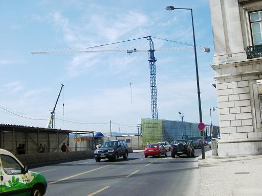
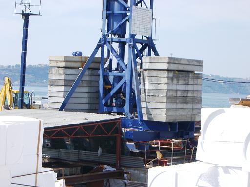
Cranes on construction sites
(a)
(b)
Fig. 2-11: Cranes on construction sites
Tower cranes are common sights on construction sites. Such cranes normally have large weights placed on and around their bases, these weights ensure that the centre of mass of the crane and its applied loading lie over its base area and that the centre of mass of the crane is low increasing its stability. Fig. 2-11a shows a typical tower crane on a construction site. Concrete blocks are purposely placed on the base of the crane to lower its centre of mass to keep the crane stable as shown in Fig. 2-11b.
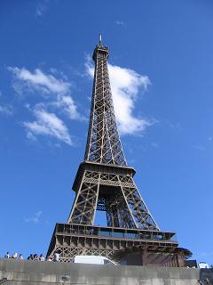
The Eiffel Tower
Fig. 2-12: The Eiffel Tower
Building structures are often purposely designed to be larger at their bases and smaller at their upper parts so that the distribution of the mass of the structure reduces with height. This lowers the centre of mass of the structure and the greater base dimensions reduce the tendency of the structure to overturn when subjected to lateral loads, such as wind. A typical example of such a structure is the Eiffel Tower in Paris as shown in Fig. 2-12. The form of the tower is reassuring and appears to be stable and safe.
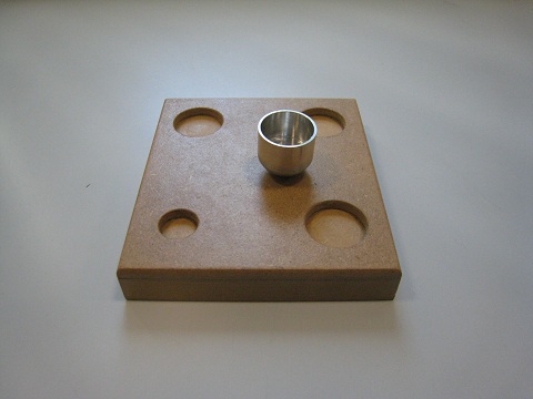
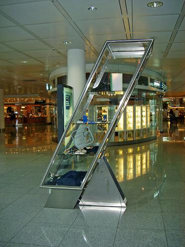
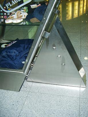
A display unit
(a)
(b)
Fig. 2-13: Inclined display unit
Fig. 2-13 shows an inclined display unit. The centre of mass of the unit is outside the base of the unit as shown in Fig. 2-13a. To make the unit stable and prevent it from overturning, a support base is fixed to the lower part of the display unit (Fig. 2-13b). The added base effectively increases the size of the base of the unit to ensure that the centre of mass of the display unit will be above the area of the new base of the unit. Thus the inclined display unit becomes stable. Other safety measures are also applied to ensure that the display unit is stable.
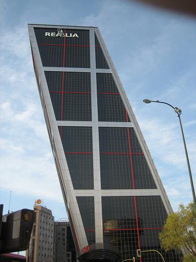
The Kio Towers
Fig. 2-14: One of the two Kio Towers
Fig. 2.14 shows one of the two 26-storey, 114m high buildings, of the Kio Towers, in Madrid, which are also known as Puerta de Europa (Gateway to Europe). The Kio Towers actually lean towards each other, each inclined at 15 degrees from the vertical.
The inclinations move the centres of mass of the buildings sideways tending to cause toppling effects on the buildings. One of the measures used to reduce these toppling effects was to add massive concrete counterweights to the basements of the buildings. This measure not only lowered the centres of the mass of each building and but also moved the centre of the mass towards a position above the centre of the base of the building.
References
2.1 Hibbeler, R C, (2005), Mechanics of Materials, Sixth Edition, Prentice-Hall Inc, Singapore, ISBN 0-13-186-638-9.