Effect of Different Cross Sections
Second moment of area (sometimes incorrectly called moment of inertia) is the geometrical property of a plane cross-section which is based on its area and on the distribution of the area.
- The further the material of the section is away from the neutral axis of the section, the larger the second moment of area of the section. Therefore the shape of a cross section will significantly affect the value of the second moment of area.
- The stiffness of a beam is proportional to the second moment of area of the cross-section of the beam.
Model Demonstrations
Two rectangular beams and an I-section beam
This demonstration shows how the shapes of cross-sections affect the stiffness of a beam.
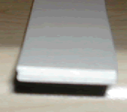
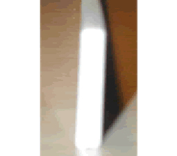
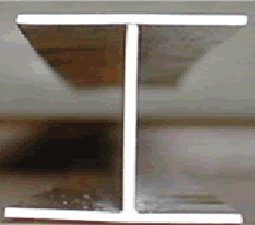
Fig. 3-4: Three beams with different cross-sections
The three beams shown in Fig. 3-4 can be made using plastic strips, each with the same amount of material, e.g. three 1mm thick by 15mm wide strips. Fig. 3-4a shows the section of the first beam in which the three strips are glued together to form a section 15mm wide and 3mm deep. The beam shown in Fig. 3-4b is the same as the first beam but its section is turned through 90 degrees. In the beam shown in Fig. 3-4c the three 1mm thick strips are arranged and glued together to form an I section. The second moments of area of the three sections about their horizontal neutral axes are in the ratios: 1 : 25 : 65 (Table 3-1). The stiffnesses of the three beams can be demonstrated and felt through simple experiments as follows:
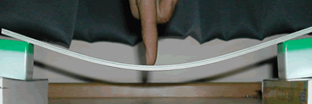
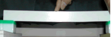
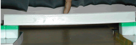
Fig. 3-5: The deflections of three beams with the same cross-section area but different second moments of area
- Support Beam 1 at its two ends, as shown in Fig. 3-5a, and press down at the mid-span of the beam. Notice and feel that the beam sustains a relatively large deflection under the applied load. This beam has a small value of second moment of area because the material of the cross-section is close to its neutral axis.
- Replace Beam 1 with Beam 2. Press down at the mid-span of the beam whilst also supporting one end of the beam to prevent its tendency to twist (Fig. 3- 5b). Note that Beam 2 deflects much less than Beam 1 and that its stiffness feels noticeably larger. The material of the cross-section in Beam 2 has been distributed farther away from its neutral axis than was the case for Beam 1, significantly increasing its second moment of area.
- Replace Beam 2 with Beam 3 and again press down at the mid-span as shown in Fig. 3-5c. The beam is stable and feels even stiffer than the rectangular beam shown in Fig. 3-5b. The increased stiffness is due to the fact that two thirds of the material of the cross section is placed in the flanges, i.e. as far away as possible from the neutral axis of the section.
The simple demonstration shows that the I-section Beam 3 is significantly stiffer than the other two beams and that Beam 2 is much stiffer than Beam 1, although all use the same amount of material.
Lifting a book using a bookmark
This demonstration shows again how the shapes of cross-sections affect the stiffness of a member.
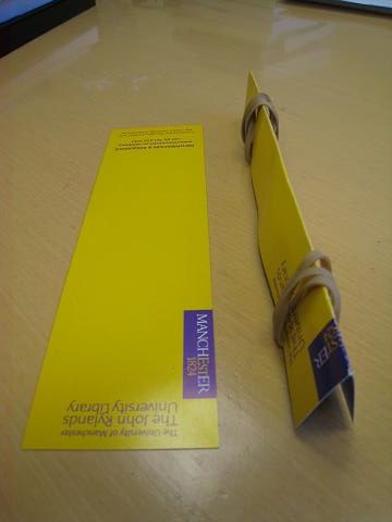
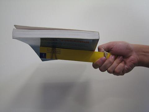
Fig. 3-6: Effect of shape of bookmarks
Fig. 3-6a shows two identical bookmarks which are strips of card with length 210 mm, width 6 mm and approximate thickness 0.4 mm. The lower bookmark in Fig. 3-6a is in its original flat form and the upper one is folded and secured with rubber bands to form the V shape as shown.
If one tries to lift a book using the bookmark in its flat form, the bookmark bends and changes its shape significantly and the book cannot be lifted. This is because the bookmark is very thin and has a small second moment of area around the axis passing through the mid thickness of the bookmark, parallel to its width, resulting in a stiffness which is too small to resist the loading.
It is however easy to lift the book using the bookmark in its folded form as shown in Fig. 3-6b. This is because the folded bookmark has a much larger second moment area since the material is distributed further away from its neutral axis than in the flat form, providing sufficient stiffness to resist the deformation induced by the book. As calculated in Example 3-2, the member with the V shaped section has the stiffness about 5000 times of that of the member of the flat section.
Practical Examples
A steel framed building
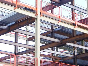
I-section members are the most commonly used structural elements in steel building frames. Fig. 3-7 shows typical steel framed building using I shaped sections for both beams and columns.
A railway bridge:
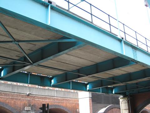
Fig. 3-8 shows a railway bridge. Both the longitudinal and transverse beams are steel I-sections and are used to support the precast concrete slabs of the deck.
I section members with holes (cellular beams and columns)
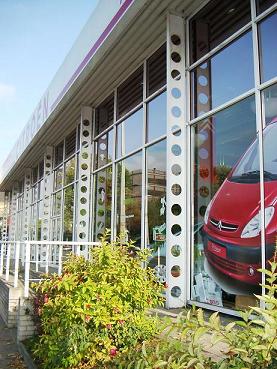
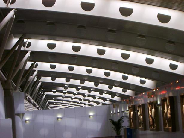
As the material close to the neutral axis of a section does not contribute efficiently to the second moment of area and hence the stiffness of a member, this material can be removed making the member lighter and saving material. It is quite common to see I section beams and columns with holes along their neutral axes.
Fig. 3-9 shows a car showroom in which the external columns support the roof. The external columns are all I sections with material around their neutral axes removed to create a lighter structure of more elegant appearance. Cellular columns are most effective in cases where axial loads are small. Fig. 3-10 shows cellular beams used in an airport terminal.
References
3.1 Gere J M, (2004), Mechanics of Materials, Thomson Books/Cole, Belmont, USA, ISBN 0-534-41793-0.