Pendulum Systems
A simple gravity pendulum consists of a massless string with one end attached to a weight and the other end fixed. When an initial push is given, the pendulum will swing back and forth under the influence of gravity.
A rotational suspended system: a rigid body is suspended by two massless strings/hangers of equal length, fixed at the same point and the body rotates about the fixed point in the plane of the strings.
A translational suspended system: a rigid body is suspended by two parallel and vertical massless strings/hangers with equal length and the strings rotate about their own fixed points. Thus the rigid body moves in parallel to its static position in the plane of the strings.
- The natural frequency of a simple pendulum is independent of its mass and only relates to the length of the massless string.
- The natural frequency of a translational suspended system is independent of its mass and the location of its centre of mass and is the same as that of an equivalent simple pendulum.
- The natural frequency of a rotational suspended system is dependent on the location of its centre of mass but is independent of the magnitude of its mass.
- An outward inclinely suspended system is a mechanism. When it is loaded vertically and asymmetrically, it will move sideway and rotate.
- The lateral natural frequency of a suspended bridge estimated using simple beam theory will be smaller than the true lateral natural frequency.
Model Demonstrations
Natural Frequency of Suspended Systems
This model demonstration verifies Eq. 14-8 and shows the unstable equilibrium state at which the suspended system will not oscillate.


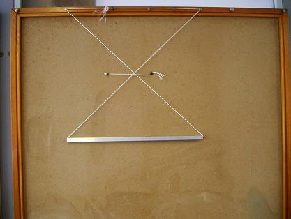
Fig. 14-4: Typical forms of a suspension system used for demonstration and tests.
A suspended system consists of a uniform hollow aluminium bar with a square section (a rigid body) and two symmetric strings to suspend the bar. The bar has a length of b =0.45m, total mass of M = 0.094 kg and moment of inertia about its centroid of ![]() . The length and the angles of the strings can be varied.
. The length and the angles of the strings can be varied.
Three typical suspension forms include vertical (Fig. 14-4a, ![]() ), outward inclined (Fig. 14-4b,
), outward inclined (Fig. 14-4b, ![]() ) and inward inclined (Fig. 14-4c,
) and inward inclined (Fig. 14-4c, ![]() ) suspension systems. In the tests, an initial lateral displacement is applied to the bar and the bar is suddenly released to generate free vibrations. The number of oscillations is counted and a stopwatch is used to record the duration of the vibrations. The swaying natural frequencies of seven different forms of suspension were measured and are listed in Table 14-2 together with the theoretical predictions obtained using Eq. 14-8. It can be seen that there is good agreement between the measured and calculated lateral natural frequencies.
) suspension systems. In the tests, an initial lateral displacement is applied to the bar and the bar is suddenly released to generate free vibrations. The number of oscillations is counted and a stopwatch is used to record the duration of the vibrations. The swaying natural frequencies of seven different forms of suspension were measured and are listed in Table 14-2 together with the theoretical predictions obtained using Eq. 14-8. It can be seen that there is good agreement between the measured and calculated lateral natural frequencies.
Figure 14-4d shows an unstable equilibrium state of the system where the two strings cross each other. An additional horizontal string is applied to prevent out-plane movement of the system. When a small movement is applied to the system, the aluminium bar moves to, and balances at, a new position without oscillation.
Table 14-2: Comparison of the measured and predicted lateral natural frequencies
| Parameters | Experiment | Theory | error |
| q =0 o , l =0.415m | 0.778Hz | 0.774Hz | -0.5% |
| q =-10.15 o , l =0.431m | 0.773Hz | 0.769Hz | -0.5% |
| q =-22.28 o , l =0.825m | 0.543Hz | 0.536Hz | -1.3% |
| q =-30.69 o , l =0.485m | 0.718Hz | 0.717Hz | -0.1% |
| q =-52.7 o , l =0.584m | UES | UES | – |
| q =24.66 o , l =0.405m | 0.930Hz | 0.929Hz | -0.1% |
| q =48.4 o , l =0.324m | 1.67Hz | 1.71Hz | 2.4% |
Effect of Added Masses
The models demonstrate that the natural frequency of a translational suspended system is independent of its mass and the location of the centre of the mas,s and is the same as that of an equivalent simple pendulum.
Fig. 14-5 shows another simple pendulum system. A plate is suspended by four strings through four holes at the corners of the plate. The other ends of the four strings are fixed to two cantilever frames as shown in Fig. 14-5. The strings are vertical when viewed from an angle perpendicular to the plane of the frame and are inclined when viewed in the plane of the frame.
When the plate moves in the plane of the steel frames, it forms a translational pendulum system in which the plate remains horizontal during its motion.
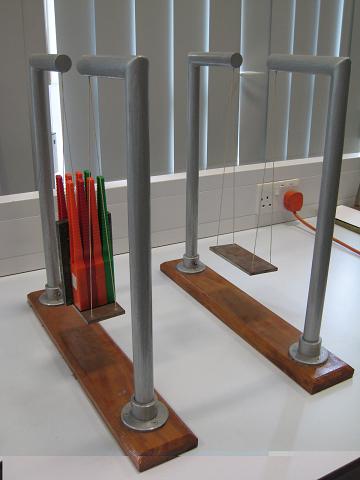
Fig. 14-6 shows two similar translational suspended systems in which the masses sway in the plane of the supporting frames. Eight magnetic bars and a steel block are placed on the plate of one suspended system to raise the centre of mass of the system. Applying the same displacement to the two plates in the planes of the frames and releasing them simultaneously, it can be observed that the two suspended systems with different masses and different centres of mass sway at the same frequency. This demonstrates that the natural frequency of a translational pendulum system is independent of its mass and the location of the centre of mass.
The suspended systems in Fig. 14-6 can also be used as two identical rotational suspended systems when the plates sway perpendicularly to the planes of the frames. Applying the same displacements to the two plates in the direction perpendicular to the frames and then releaseing them simultaneously, it can be observed that the plate with the added weights oscilates faster than the other plate.
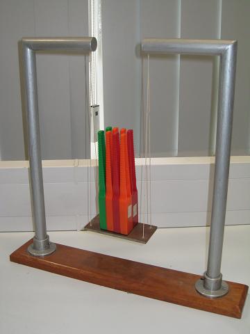
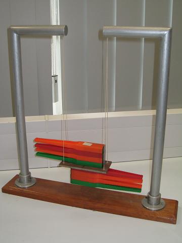
Fig. 14-7: Effect of the centre of mass
Fig. 14-7 show two arrangements of eight identical magnetic bars. In one case the eight bars stand on the plate (Fig. 14-7a) and in the other case four magnetic bars are placed on the top and bottom surfaces of the plate respectively (Fig. 14-7b). The two cases have the same amount of mass but different centres of mass. Conducting the same experiment as before for the rotational suspended systems, it can be seen that the system with standing bars oscillates faster than that with horizontal bars.
The systems shown in Figs. 14-5 and 14-7b have different amounts of mass but the same location of the centre of mass. If the oscillations of the two systems shown are generated by giving the same initial displacements in the plane perpendicular to the framnes, it can be observed that the two systems oscillate at the same frequency.
The two sets of experiments demonstrate that the natural frequency of a rotational suspended system is dependent on the location of its centre of mass but is independent of the magnitude of its mass.
Table 14-3 compares the times recorded for 30 oscillations of the translational and rotational suspended systems with added masses. Each case was tested twice.Table 14-3: Comparison of the times for 30 oscillations of the suspended systems
| Translational SuspendedSystems (seconds) | Rotational SuspendedSystems (seconds) | |
| Empty (Fig. 14-5) | 34.3, 34.4 | 34.4, 34.5 |
| With full weights (Fig. 14-6) | 34.3, 34.5 | 32.3, 32.4 |
| With magnetic bars placed vertically(Fig. 14-7a) | 34.2, 34.2 | 33.4, 33.3 |
| With magnetic bars placed horizontally(Fig. 14-7b) | 34.2, 34.3 | 34.3, 34.3 |
Effect of mass on the oscillation of a transverse suspended-system
Effect of mass on the oscillation of a rotational suspended-system
Static Behaviour of an Outward Inclined Suspended System
This demonstration shows that an outward inclinely suspended system is a mechanism that moves sideway if a vertical load is applied asymmetrically on the plate.
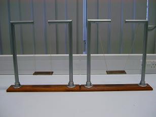
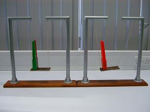
Fig. 14-8: Static behaviour of of an outward inclined suspended system.
Consider two suspended systems, where a steel plate is suspended by two vertical strings and the same plate is suspended by two symmetrically outward inclined strings, as shown in Fig. 14-8.
Place similar weights asymmetrically on the two plates as shown in Figure 14.8b. It can be observed that the vertically suspended system does not experience any lateral movement while the outward inclinely suspended system undergoes both lateral and rotational movements.
For the vertically suspended system, the vertical and lateral movements are independent and the vertical load only induces vertical deformations of the strings with little rotation due to the difference of the elastic elongation of the strings. For the plate suspended by the two outward inclined strings, the horizontal and rotational movements of the plate are coupled. The movements relate to the geometry of the system rather than the elastic elongation of the strings.
Practical Examples
An Inclined Suspended Wooden Bridge in a Playground

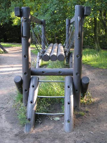
Fig. 14-9: An inclinly suspended wooden bridge in a playground
As demonstrated in Section 14.3.3, an inclined suspended system moves sideway if a vertical load is applied asymmetrically. The phenomenon should be avoided in engineering structures, as it may lead to unsafe structures. However, Fig. 14-9 shows an outward inclinely suspended wood footbridge in a playground. The bridge is purposely built in such a way so that the bridge wobbles when a child walks on the bridge, creating excitement and a challenge for crossing the bridge.
Seismic Isolation of a Floor
Fig. 14-10: A translational suspended floor (Courtsy of Porf. M Kawaguchi)
As the natural frequency of a translational suspended system is only governed by its length and is independent of its mass, the concept of a pendulum seismic isolator was developed and used in Japan.
As the natural frequency of a translational suspended system is only governed by its length and is independent of its mass, the concept of a pendulum seismic isolator was developed and used in Japan.
The Foucault Pendulum
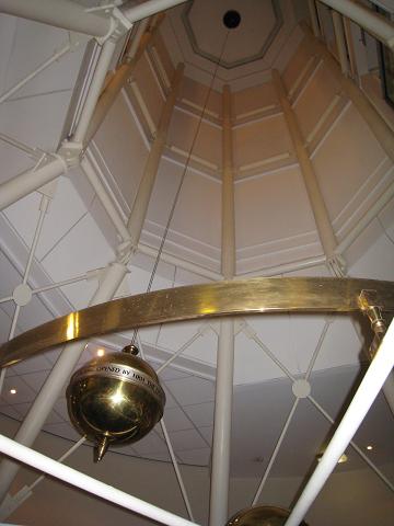
Fig. 14-11: The Foucault pendulum
Fig. 14-11 shows a huge brass pendulum that swings across the lower foyer in the Manchester Conference Centre at the University of Manchester. The pendulum was set up as a tribute to Jean Bernard Leon Foucault.
Jean Bernard Leon Foucault (1819 – 1868), a French physicist, demonstrated the earth’s rotation using his famous pendulum. He suspended a 28 kg bob with a 67 m wire from the dome of the Pantheon in Paris. Foucault was acclaimed by witnesses for proving that the earth does indeed spin on its axis. As the plane of the pendulum oscillation remained unchanged with the stars, they could understand that the Pantheon moved around the pendulum, and not vice-versa!
Foucault’s pendulum was the first dynamical proof of the earths rotation in an easy-to-see experiment.
References
14.1 Matthews, M R, Gauld C F and Stinner, A, (2005), The Pendulum: Scientific, Historical, Philosophical and Educational Perspectives, pp. 37-47, Springer Netherlands, Dordrecht, ISBN 978-1-4020 3525 8.
14.2 Zou, D and Ji, T, (2008), Dynamic characteristics of a generalised suspension system, International Journal of Mechanical Sciences, Vol. 50, pp. 30-42.