Free Vibration
Free vibration : A structure is said to undergo free vibration when it is disturbed from its static stable equilibrium position by an initial displacement and/or initial velocity and then allowed to vibrate without any external dynamic excitation.
Period of vibration: The time required for an undamped system to complete one cycle of free vibration is the natural period of vibration of the system.
Natural frequency : The number of cycles of free vibration of an undamped system in one second is termed the natural frequency of the system, and is the inverse of the period of vibration.
A SDOF system : If the displacement of a system can be uniquely determined by a single variable, this system is called a single-degree-of-freedom (SDOF) system. Normally it consists of a mass, a spring and a damper. The square of the natural frequency of a SDOF system is proportional to the stiffness of the system and the inverse of its mass.
A generalised SDOF system : Consider a discrete system that consists of several masses, springs and dampers, or a continuous system that has distributed mass and flexibility. If the shape or pattern of its displacements is known or assumed, the displacements of the system can then uniquely be determined by its magnitude (a single variable). This system is termed as a generalised SDOF system. The analysis developed for a SDOF system is applicable to a generalised SDOF system.
- For a structure with a given mass, the stiffer the structure, the higher the natural frequency.
- The larger the damping ratio of a structure, the quicker the decay of its free vibration.
- The higher the natural frequency of a structure, the quicker the decay of its free vibration.
- The fundamental natural frequency reflects the stiffness of a structure. Thus it can be used to predict the displacement of a simple structure. Also the displacement of the structure can be used to estimate its fundamental natural frequency.
Model Demonstrations
Free vibration of a pendulum system
This demonstration shows the definitions of natural frequency and period of a simple system.
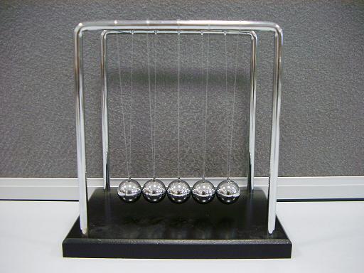
Fig. 15-8 shows a pendulum system consisting of five balls suspended by strings with equal length (known as Newton’s cradle). Push the balls in a direction parallel to the plane of the frames to apply an initial displacement and release the balls. The balls then move from side to side in free vibration at the natural frequency of the system.
Count the number of oscillations of the balls in 30 seconds and the number of oscillations divided by 30 is the natural frequency of the oscillations of the pendulum system in cycles per second or Hz. The inverse of the natural frequency is the period of the oscillations. For the studied system, 40 cycles of oscillation in 30 seconds were counted. Thus the natural frequency of the system is 40/30 = 1.33 Hz and the period is 1/1.33 = 0.75s.
The vertical distance between the supports of the strings and the connecting points on the balls is 140mm so the theoretical value of the natural frequency is:
![]()
Vibration decay and natural frequency
This set of models demonstrates that the higher the natural frequency of a structure, the quicker the decay of its free vibration.
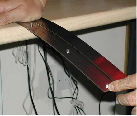

Fig. 15-9: The decay of free vibration and the natural frequencies of members
A single steel ruler and a pair of identical steel rulers, bolted firmly together, are placed side by side as cantilevers shown as in Fig. 15-9a. Give the ends of the two cantilevers the same initial displacement and release them suddenly at the same time (Fig. 15-9a). Free vibrations of the rulers follow and it will be observed that the bolted double ruler stops vibrating much more rapidly than the single ruler (Fig. 15-9b).The rate of decay of free vibration is proportional to the product of the damping ratio and the natural frequency of the structure as shown in Eq. 15-15 and Example 15-1. The bolted double ruler has a higher natural frequency since its second moment of area is 8 times of that of the single ruler, making it 8 times as stiff as the single ruler, while its mass is just double of that of the single ruler. In fact the fundamental natural frequency of the bolted double ruler is twice that of the single ruler. The damping ratios for the two cantilevers can be considered to be the same. Hence this demonstration verifies the concept that the higher the natural frequency of a structure, the quicker the decay of its free vibration.
An overcritically-damped system
This demonstration shows the movement rather than the vibrations of an overcritically-damped beam subject to an initial displacement.
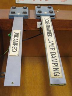
Fig. 15-10 shows two cantilever metal strips representing two cantilever beams. The one on the left is a conventional metal strip and the one on the right uses two metal strips with a layer of damping material constrained between the two strips. Apply the same initial displacement on the free ends of the two cantilevers and release them at the same time. It is observed that the cantilever on the right returns to its original position slowly without experiencing any vibration. This is the phenomenon of an overcritically-damped system described in Section 15.2.1 and Fig. 15-3.
Mode shapes of a discrete model
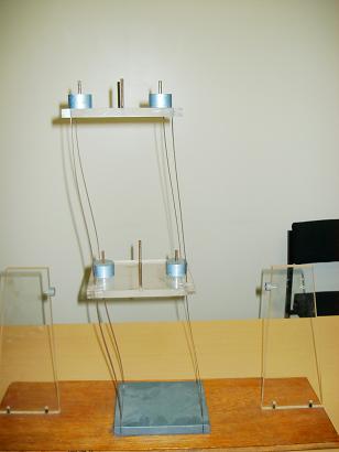
This demonstration shows the two mode shapes of a discrete TDOF system.
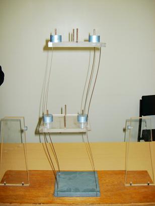
15-11: Mode shapes of a TDOF model
Fig. 15-11 shows a two degree-of-freedom (TDOF) model that has two natural frequencies and two vibration modes. Apply initial horizontal displacements of the two masses in the same direction and then release them at the same time, the first mode of vibration is generated, Fig. 15-11a. Apply initial horizontal displacements of the two masses in opposite directions and then release them at the same time, the second mode of vibration is generated, Fig. 15-11b.
Mode shapes of a continuous model
This demonstration shows the shapes of the first two modes of vibration of a continuous beam.
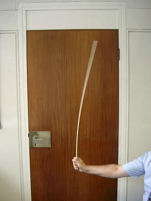
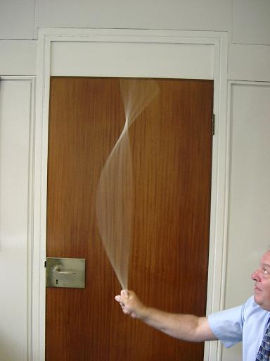
Fig. 15-12: Mode shapes of a cantilever
Take a long plastic strip and hold one end of the strip as shown in Fig. 15-12. Then move the hand forward and backward slowly, it generates the first mode of vibration as shown in Fig. 15-12a. Do the same but increase the speed of the movement, it excites the second mode of vibration as given in Fig. 15-12b. The two mode shapes of the strip are similar to those shown in Fig. 15-7.
Tension force and natural frequency of a straight tension bar
This experiment verifies Eq. 15-38 and shows that the force in a tension bar can be predicted using natural frequency measurement.
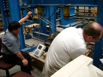
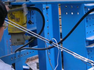
Fig. 15-13: Verification test of a tension bar
Two steel bars with different diameters (6mm and 8mm) and lengths (2.55m and 2.73m) were fixed to the steel frame shown in Fig. 15-13a. Two strain gauges were glued on each of the bars opposite to each other at the mid-points of the bars. Tension forces were applied by through turnbuckles at the ends of the bars, and the values of forces were determined through strain measurements. A small accelerometer was fixed to one of the two bars as shown in Fig.15-13b to record vibrations.
Vibration tests of the tension bars were conducted and accelerations were recorded when the bars were tensioned to different levels. Fundamental natural frequencies were determined from spectral analysis of the acceleration responses. For a range of measured fundamental natural frequencies Table 15-3 compares the measured tension forces in the 6mm tension bar and the forces predicted using Eq. 15-38 where the measured fundamental natural frequency values were taken. For predictions, the following values were used:
![]() ,
, ![]() and
and ![]() .
.
Table 15-3: Comparison of the measured and predicted tension forces for 6mm bar [15.5]
Experimental Results
Experimental Results
Prediction using Eq. 15-38
Prediction using Eq. 15-38
Natural frequency (Hz)
Tension force ( kN )
Tension force
( kN )Relative error (%)
13.9
1.16
1.16
0.00
15.5
1.42
1.39
2.11
16.9
1.70
1.65
2.94
18.3
1.98
1.93
2.53
19.6
2.25
2.22
1.33
20.5
2.50
2.43
2.80
21.9
2.77
2.77
0.00
22.8
3.05
3.00
1.67
It can be seen from Table 15-3 that the tension forces in a tensioned bar can be predicted using Eq.15-38 and the natural frequency measurements.
Environmental effects such as air movements around a structure can also induce vibrations, though such vibration may be very small. These types of vibration may not be exactly free vibration as they are caused by disturbances due to external effects, such as wind. However, the concept of free vibration can still be used to identify the natural frequencies of a structure.
Practical Examples
A musical box
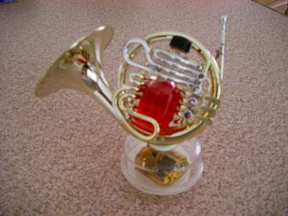
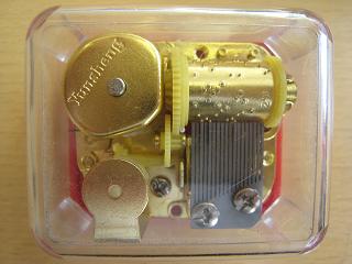
Fig. 15-14: A musical box and its core (The models are provided by Prof. B Zhuang, Zhejiang University, China)
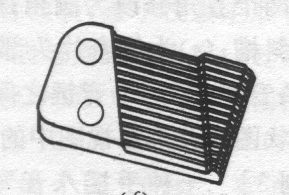
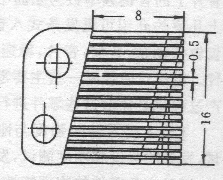
Fig. 15-15: Cantilever beams with different lengths and sections in the music box (mm)
A musical box is a device that produces music using mechanical vibration. Fig. 15-14a shows one of many decorative music boxes which are readily available. The core of the music box is the unit show in Fig. 15-14b.
A musical box is a device that produces music using mechanical vibration. Fig. 15-14a shows one of many decorative music boxes which are readily available. The core of the music box is the unit show in Fig. 15-14b.
A given musical note relates to a particular natural frequency of the vibrating body. Table 15-4 gives the relationships between some natural frequencies and music notes.
Table 15-4: Relations between natural frequency and music note
| Natural frequency (Hz) | 261.6 | 293.7 | 329.6 | 349.2 | 392 | 440 | 493.9 |
| Music note | (Middle) C | D | E | F | G | A | B |
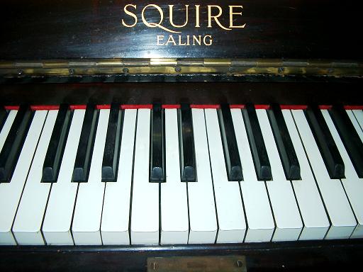
Fig. 15-16 shows part of the keyboard of a piano. The main reference point on a piano is known as Middle C. This is the white note located approximately in the centre of the keyboard and immediately to the left of a pair of black keys. Striking the Middle C key, the sound generated corresponds to a frequency of 262 Hz. The next white key, D, to the right of the Middle C key, produces a sound corresponding to a frequency of 294 Hz.
Measurement of the fundamental natural frequency of a building through free vibration generated using vibrators
When the free vibrations of a structure can be measured as accelerations, velocities or displacements, the natural frequencies of the structure can be determined from their vibration time histories.
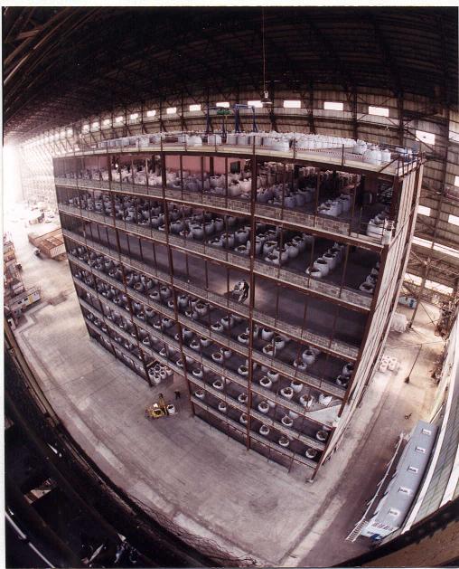
Fig. 15-17 shows an eight-storey steel framed test building in the Cardington Laboratory of the Building Research Establishment Ltd. Different dynamic test methods were used to determine the natural frequencies of this building. One of the methods used was to record the free vibrations of the building [15.8].
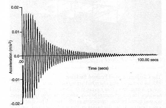
Four vibrators mounted at the corners of the roof of the building were used to generate movement of the structure. Once movement was initiated the vibrators were turned off and the resulting free vibrations of the structure were measured by accelerometers. Fig. 15-18 shows the acceleration-time history of the decayed vibrations. The frequency of the oscillations, which is a natural frequency of the structure, was determined from the time history as the inverse of the time interval between two successive acceleration peaks.
Measurement of the natural frequencies of a stack through vibration generated by the environment
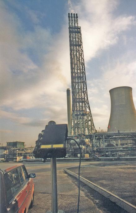
Fig. 15-19 shows a 97.5m tall multiflare stack which can be used to burn off excess gases. A laser test system was set up approximately 100m from the stack to monitor the stack vibrations. Several velocity-time histories on selected measurement points of the stack were measured when wind was blowing.
The natural frequencies of 0.67 Hz and 0.73 Hz were measured which corresponded to the fundamental modes in the two orthogonal horizontal directions.
The tension forces in the cables in the London Eye
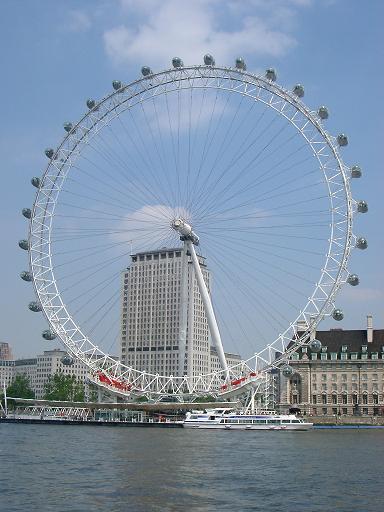
The wheel of the London Eye is stiffened by cables as shown in Fig. 15-20. There are 16 rim rotation cables, each around 60mm thick. In addition, there are 64 spoke cables, which are all 70mm thick and are spun from 121 individual strands in layers. Part of the tension in the cables will be lost due to normal operations after a period of time. Thus the cables need to be re-tensioned to maintain their design values. It is not convenient to measure the tension force directly in each of the cables. Instead, transverse impact loads are applied to each cable to generate free vibrations, from which the fundamental natural frequency of the cable in the transverse direction can be determined. Using the measured fundamental natural frequency, the tension in each cable can be predicted using Eq. 15-38 or similar equations. Tension losses can then be identified and recovered.
A toilet seat-cover
When turning the seat cover of a toilet down, one has to hold the cover and move it down to the toilet seat. Otherwise, the cover would impact on the seat and generate a loud sound. How could this be avoided?
It is demonstrated in a video clip in Model 3 of this chapter that an over-critically damped steel strip returns to its original position slowly and smoothly without experiencing vibration. This concept has been developed and used to design the seat-covers of some modern toilets. The video below shows how the cover moves slowly and gradually to the toilet seat without holding it.
The principle is also used for closing doors and for closing the covers of pianos:
(Courtesy of Prof. B Zhuang, Zhejiang University, China)
References
15.1 Beards, C F, (1996), Structural Vibration: Analysis and Damping, Arnold, London, IBSN 0 340 64580 6.
15.2 Clough, R W and Penzien J, (1993), Dynamics of Structures, McGraw-Hill, New York, ISBN 0-07-11324-4.
15.3 Chopra, A K, (1995), Dynamics of Structures, Prentice Hall Inc, New Jersey, ISBN 0-13-521063-1.
15.4 Morse, P M, (1948), Vibration and Sound, Second Edition, McGraw-Hill Book Company, New York.
15.5 Tzima, K, (2003), Predicting tension of a stayed cable using frequency measurements, MSc Dissertation, UMIST, UK.
15.6 Zhuang, B, et al, (1996), Design of music boxes and vibration of tuning bars, New Times Press, China, ISBN 7-5042-0307-6.
15.7 White, H E and White, D H, (1980), Physics and Music – the science of musical sound, Saunders College, Philadelphia, ISBN 0-03-045246-5.
15.8 Ellis, B. R. and Ji, T., (1996), Dynamic testing and numerical modelling of the Cardington steel framed building from construction to completion, The Structural Engineer, Vol.74, No.11, pp.186-192.